
ᐅ Hydraulic balancing for air-to-water heat pump + high-efficiency circulation pump
Created on: 3 Jan 2021 23:07
L
lesmue79
Warning: wall of text and lots of theorycrafting:
I am currently trying to optimize or fundamentally adjust the hydraulic and thermal balancing of my air-to-water heat pump system, including underfloor heating, but I am running into the following issues:
First, about the house: KfW-55 bungalow with controlled mechanical ventilation
Nearly 105 m2 (1130 ft²) of heated floor area
Air-to-water heat pump with underfloor heating throughout, 10cm (5 inches) pipe spacing, max 30°C (86°F) flow temperature. At -12°C (10°F) outside temperature, the calculated heating load is 3276 watts.
According to the datasheet, the heat pump delivers 3200 watts at -10°C (14°F) outside temperature with flow 35°C (95°F) and return 30°C (86°F).
All rooms are designed for 20°C (68°F), including the bathroom (to avoid an oversized heat pump by the general contractor). Additionally, for the bathroom, an electric radiator is planned to achieve a room temperature of 2°C (4°F) higher than the rest. However, in reality, the toilet, utility room, bedroom, and guest room should only be heated to 18°C (64°F) (it won’t be much lower in a new building). The bathroom is intended to be warmer, at around 21–22°C (70–72°F).
Currently, I have the following questions (though perhaps I am too focused on the self-regulation effect and avoiding actuator valves):
1. Circulation pump: Various guides, manuals, and forum posts recommend setting the circulation pump of the underfloor heating to a constant flow rate.
My conclusion: my circulation pump is a high-efficiency variable-speed pump, so I can set the flow rate on the manifold in L/min (based on the calculations from the general contractor / heating engineer) to whatever I want, but the flow always settles around 600–630 L/h (10–11 L/min). The only significant flow changes I get are when I activate the actuators and room thermostats, which then open or close the valves. The only adjustment parameter on the circulation pump is the minimum flow rate; no other settings are available. But I don’t fully understand how this function works.
2. Operating times of the heat pump / self-regulation: I usually read that the heat pump should run as long as possible, though some sources say short cycling a few times is normal.
My conclusion: if I run the system without actuators and room thermostats, the energy integral control does not work; the system basically runs almost 24/7 at low temperatures, with interruptions only for defrosting. As a result, with a flow temperature of 27°C (81°F), I only get about 19–20°C (66–68°F) room temperature, but I’d prefer around 21–23°C (70–73°F), especially in the bathroom. If I do it the other way, with energy integral control (EIC) and actuators and slightly higher curve so that 30°C (86°F) flow is demanded, the actuators close in the first rooms, which causes the flow to increase to the other rooms because the pump still distributes the volume flow among the remaining open valves. At the same time, the flow temperature rises for rooms where the actuators are still open until the desired temperature is reached and the actuators close. Then the energy integral kicks in and goes negative because actual flow temperature exceeds setpoint flow temperature, until the heat pump shuts off once the energy integral has been reduced.
So right now, I’m struggling with what is better: should the system just run steadily at a flow temperature of 27°C (81°F) (which I might still optimize a bit), with heating only interrupted for defrosting or when the compressor’s hysteresis is exceeded, causing the compressor to be locked out for a certain time? Or should I define time windows during which the system is allowed to operate?
Maybe I could manage this better by refining the balancing, but I guess I’ll have to throttle down so much for the energy integral to work that the flow rate will fall below the minimum required, and the bypass valve will open.
Or should I run the system at 30°C (86°F) flow with room thermostats and actuators, allowing the energy integral control to function properly and reach the desired room temperatures?
Another strange issue is: according to the heating load and underfloor heating calculations, the system requires about 840 L/h (14 L/min) at 4.4 K (7.9°F) delta T in the design case. If I set the flow according to this calculation or slightly lower, the pump only delivers 600–630 L/h (10–11 L/min) at a delta T of about 3–4 K (5.4–7.2°F).
According to the datasheet, the optimal flow rate for the heat pump is 540 L/h (9 L/min) at 5 K (9°F) delta T.
540 L/h * 5 K * 1.163 = 3132 watts
620 L/h * 3.5 K * 1.163 = 2527 watts
840 L/h * 4.4 K * 1.163 = 4287 watts
Calculated heating load at -12°C (10°F) = 3176 watts (and this heating load is probably overestimated since controlled mechanical ventilation was not included in the calculation, and I want only 15–18°C (59–64°F) in four rooms instead of the calculated 20°C (68°F). Also, average outside temperatures for the heat pump in my area are closer to -10°C (14°F) rather than -12°C (10°F), so there is some margin).
Maybe I have now gotten too caught up in theoretical and calculated values and can’t see the forest for the trees?
I am currently trying to optimize or fundamentally adjust the hydraulic and thermal balancing of my air-to-water heat pump system, including underfloor heating, but I am running into the following issues:
First, about the house: KfW-55 bungalow with controlled mechanical ventilation
Nearly 105 m2 (1130 ft²) of heated floor area
Air-to-water heat pump with underfloor heating throughout, 10cm (5 inches) pipe spacing, max 30°C (86°F) flow temperature. At -12°C (10°F) outside temperature, the calculated heating load is 3276 watts.
According to the datasheet, the heat pump delivers 3200 watts at -10°C (14°F) outside temperature with flow 35°C (95°F) and return 30°C (86°F).
All rooms are designed for 20°C (68°F), including the bathroom (to avoid an oversized heat pump by the general contractor). Additionally, for the bathroom, an electric radiator is planned to achieve a room temperature of 2°C (4°F) higher than the rest. However, in reality, the toilet, utility room, bedroom, and guest room should only be heated to 18°C (64°F) (it won’t be much lower in a new building). The bathroom is intended to be warmer, at around 21–22°C (70–72°F).
Currently, I have the following questions (though perhaps I am too focused on the self-regulation effect and avoiding actuator valves):
1. Circulation pump: Various guides, manuals, and forum posts recommend setting the circulation pump of the underfloor heating to a constant flow rate.
My conclusion: my circulation pump is a high-efficiency variable-speed pump, so I can set the flow rate on the manifold in L/min (based on the calculations from the general contractor / heating engineer) to whatever I want, but the flow always settles around 600–630 L/h (10–11 L/min). The only significant flow changes I get are when I activate the actuators and room thermostats, which then open or close the valves. The only adjustment parameter on the circulation pump is the minimum flow rate; no other settings are available. But I don’t fully understand how this function works.
2. Operating times of the heat pump / self-regulation: I usually read that the heat pump should run as long as possible, though some sources say short cycling a few times is normal.
My conclusion: if I run the system without actuators and room thermostats, the energy integral control does not work; the system basically runs almost 24/7 at low temperatures, with interruptions only for defrosting. As a result, with a flow temperature of 27°C (81°F), I only get about 19–20°C (66–68°F) room temperature, but I’d prefer around 21–23°C (70–73°F), especially in the bathroom. If I do it the other way, with energy integral control (EIC) and actuators and slightly higher curve so that 30°C (86°F) flow is demanded, the actuators close in the first rooms, which causes the flow to increase to the other rooms because the pump still distributes the volume flow among the remaining open valves. At the same time, the flow temperature rises for rooms where the actuators are still open until the desired temperature is reached and the actuators close. Then the energy integral kicks in and goes negative because actual flow temperature exceeds setpoint flow temperature, until the heat pump shuts off once the energy integral has been reduced.
So right now, I’m struggling with what is better: should the system just run steadily at a flow temperature of 27°C (81°F) (which I might still optimize a bit), with heating only interrupted for defrosting or when the compressor’s hysteresis is exceeded, causing the compressor to be locked out for a certain time? Or should I define time windows during which the system is allowed to operate?
Maybe I could manage this better by refining the balancing, but I guess I’ll have to throttle down so much for the energy integral to work that the flow rate will fall below the minimum required, and the bypass valve will open.
Or should I run the system at 30°C (86°F) flow with room thermostats and actuators, allowing the energy integral control to function properly and reach the desired room temperatures?
Another strange issue is: according to the heating load and underfloor heating calculations, the system requires about 840 L/h (14 L/min) at 4.4 K (7.9°F) delta T in the design case. If I set the flow according to this calculation or slightly lower, the pump only delivers 600–630 L/h (10–11 L/min) at a delta T of about 3–4 K (5.4–7.2°F).
According to the datasheet, the optimal flow rate for the heat pump is 540 L/h (9 L/min) at 5 K (9°F) delta T.
540 L/h * 5 K * 1.163 = 3132 watts
620 L/h * 3.5 K * 1.163 = 2527 watts
840 L/h * 4.4 K * 1.163 = 4287 watts
Calculated heating load at -12°C (10°F) = 3176 watts (and this heating load is probably overestimated since controlled mechanical ventilation was not included in the calculation, and I want only 15–18°C (59–64°F) in four rooms instead of the calculated 20°C (68°F). Also, average outside temperatures for the heat pump in my area are closer to -10°C (14°F) rather than -12°C (10°F), so there is some margin).
Maybe I have now gotten too caught up in theoretical and calculated values and can’t see the forest for the trees?
T
T_im_Norden6 Jan 2021 12:12If the heating curve cannot be lowered any further, you can still adjust the base temperature; it might also be possible to limit the heat pump side supply temperature.
D
Daniel-Sp6 Jan 2021 12:55lesmue79 schrieb:
Update:
Attached are the latest room temperatures, but I suspect they have increased partly due to the slightly higher outdoor temperature and additional heat sources. Primarily, the activation of the heating circuits with higher flow rates is causing the temperature to rise significantly. The small difference in outdoor temperature will not have such a strong impact inside the house.
I would start adjusting the system now. Reduce the flow rate in the bedroom to 0.5 (no unit given, assumed liters per minute) initially, and do the same in the utility room. Leave the rest as is. If the bedroom becomes cooler, you will lose heat in the bathroom, so I would initially avoid changing the flow in the guest room. Is the bathroom located above the utility room?
After 1-2 days, make new decisions based on the results.
Since this is a bungalow, all rooms are next to each other. The bathroom could become problematic, as already noted, if I reduce the flow too much to the adjacent bedroom and guest room. I would even consider reducing the flow to the technical/laundry room to the minimal possible level, because the room will be warm enough anyway due to external factors like the inverter, dryer, heating circuit distributor, and similar devices.
To avoid misunderstandings regarding the plan: the heating circuit distributor is not located in the hallway but in the utility room behind the door, essentially under the meter cabinet opposite the heat pump.
Regarding the supply temperatures, I can set minimum and maximum supply temperatures for the heating circuit. Additionally, I could limit this further through the compressor hysteresis.
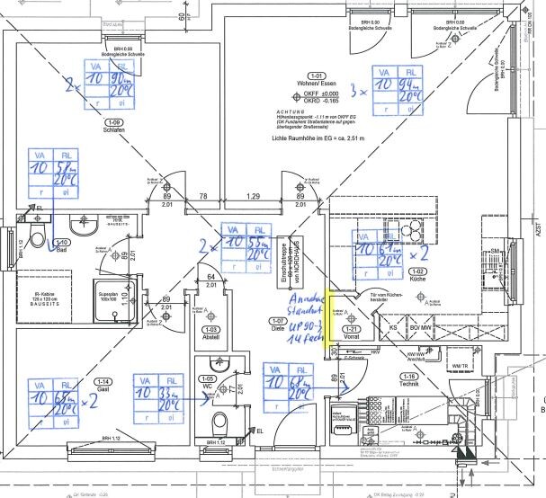
To avoid misunderstandings regarding the plan: the heating circuit distributor is not located in the hallway but in the utility room behind the door, essentially under the meter cabinet opposite the heat pump.
Regarding the supply temperatures, I can set minimum and maximum supply temperatures for the heating circuit. Additionally, I could limit this further through the compressor hysteresis.
T
T_im_Norden6 Jan 2021 14:24Then there is enough leeway to achieve that efficiently.
Once I get to the point of accessing the flow rates, my plan as of today is:
Reduce the flow rate for the toilet...
Reduce the flow rate for the utility room...
and then first check where the circulation pump is pushing the flow. One heating circuit will likely benefit from the reduced flow from the toilet and utility room; that should be the one with the lowest pressure loss at that time, meaning the shortest remaining circuit. This will probably be one of the two hallway circuits, each around 35 m (115 feet).
Reduce the flow rate for the toilet...
Reduce the flow rate for the utility room...
and then first check where the circulation pump is pushing the flow. One heating circuit will likely benefit from the reduced flow from the toilet and utility room; that should be the one with the lowest pressure loss at that time, meaning the shortest remaining circuit. This will probably be one of the two hallway circuits, each around 35 m (115 feet).
T
T_im_Norden6 Jan 2021 15:56Lower the heating curve
Lower the base temperature
Limit the flow temperature
until the bathroom reaches the desired temperature fully open.
Only then would I start to reduce.
I would reduce the large circuits, like the living room as well as the utility room and bedroom, and observe how this affects the other circuits.
Lower the base temperature
Limit the flow temperature
until the bathroom reaches the desired temperature fully open.
Only then would I start to reduce.
I would reduce the large circuits, like the living room as well as the utility room and bedroom, and observe how this affects the other circuits.
Similar topics