
ᐅ Main Pipeline Layout – Wastewater Drainage and Elevation Planning
Created on: 24 Sep 2020 19:39
T
Tolentino
Hello dear forum members,
I have now received a preliminary draft of the detailed construction plan. This will be adjusted again after the structural engineering calculations are completed, if necessary, and then finalized. Until then, I have time to consider whether everything makes sense as it is.
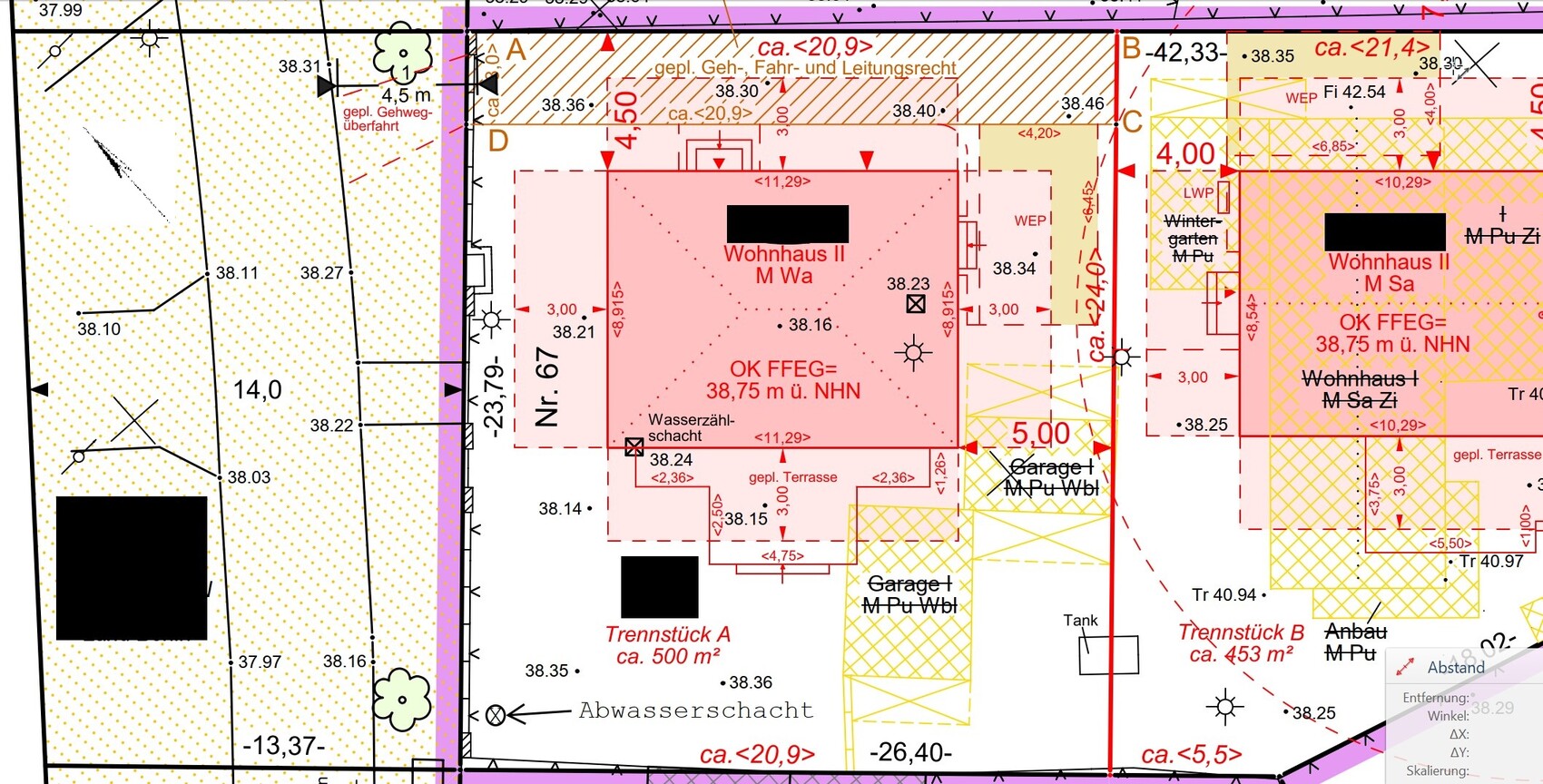
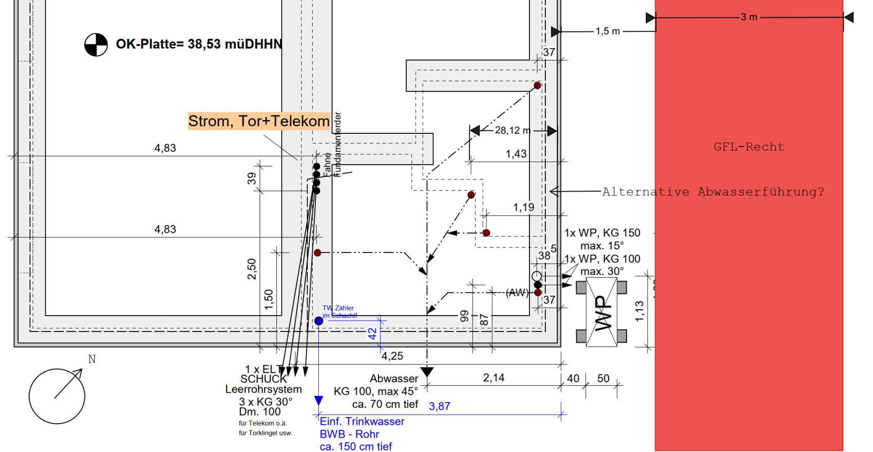
Below you can see first a site plan (from the building permit / planning permission) and a section from the draft ground drainage plan by the construction manager. Please note that the plans have different orientations, but I have added the north arrows anew in each case. In the ground drainage plan, I have marked the natural ground level (GFL) as an orange rectangle.
As you can see, the draft proposes that the wastewater pipes be combined and routed downward on the plan — that is, towards the neighboring property at the back, away from the street. This would require me to make one more directional change. The construction manager’s reasoning was that pipes should always be routed under the foundation slab on the shortest possible path because they are inaccessible afterward. That makes sense. However, looking at where the pipes come down elsewhere, is this really the average shortest route? There are more drainage pipes lying closer to the GFL strip; only the kitchen drain would be further away. Considering the longer pipe run for the main line and the additional required direction change, wouldn’t it be more sensible to route it to the right side of the plan (in the ground drainage plan) or upwards in the site plan?
The second topic is the height of the wastewater pipe. Here, the outlet height from the foundation slab is set at approximately 70 cm (28 inches) — I still need to confirm with respect to which height this refers; I assume the foundation slab’s top or underside. This is generally a standard height for wastewater pipes, but since the intended pipe route runs along the GFL, which also serves as the shared driveway for my neighbor and me, meaning it is a trafficked area, it is recommended to place the pipe deeper — from what I gather, about 150 cm (59 inches). Should I inform the general contractor about this now, or is it possible to add another step before the GFL? Especially because the existing wastewater shaft (see the west corner on the site plan) is to be used, and the pipe will have to cover a good distance of about 40 m (130 feet) to get there, the question about the actually necessary minimum height is important. The wastewater shaft is roughly 1.8 m (71 inches) deep. So, this roughly matches, but only if I can start on my preferred side of the house. If I have to go around the house, I would reach the shaft too low.
Do you have any ideas, suggestions, or remarks?
Thanks and best regards
Tolentino
I have now received a preliminary draft of the detailed construction plan. This will be adjusted again after the structural engineering calculations are completed, if necessary, and then finalized. Until then, I have time to consider whether everything makes sense as it is.
Below you can see first a site plan (from the building permit / planning permission) and a section from the draft ground drainage plan by the construction manager. Please note that the plans have different orientations, but I have added the north arrows anew in each case. In the ground drainage plan, I have marked the natural ground level (GFL) as an orange rectangle.
As you can see, the draft proposes that the wastewater pipes be combined and routed downward on the plan — that is, towards the neighboring property at the back, away from the street. This would require me to make one more directional change. The construction manager’s reasoning was that pipes should always be routed under the foundation slab on the shortest possible path because they are inaccessible afterward. That makes sense. However, looking at where the pipes come down elsewhere, is this really the average shortest route? There are more drainage pipes lying closer to the GFL strip; only the kitchen drain would be further away. Considering the longer pipe run for the main line and the additional required direction change, wouldn’t it be more sensible to route it to the right side of the plan (in the ground drainage plan) or upwards in the site plan?
The second topic is the height of the wastewater pipe. Here, the outlet height from the foundation slab is set at approximately 70 cm (28 inches) — I still need to confirm with respect to which height this refers; I assume the foundation slab’s top or underside. This is generally a standard height for wastewater pipes, but since the intended pipe route runs along the GFL, which also serves as the shared driveway for my neighbor and me, meaning it is a trafficked area, it is recommended to place the pipe deeper — from what I gather, about 150 cm (59 inches). Should I inform the general contractor about this now, or is it possible to add another step before the GFL? Especially because the existing wastewater shaft (see the west corner on the site plan) is to be used, and the pipe will have to cover a good distance of about 40 m (130 feet) to get there, the question about the actually necessary minimum height is important. The wastewater shaft is roughly 1.8 m (71 inches) deep. So, this roughly matches, but only if I can start on my preferred side of the house. If I have to go around the house, I would reach the shaft too low.
Do you have any ideas, suggestions, or remarks?
Thanks and best regards
Tolentino


Your plans are overwhelming to me as well, but the principle of always following the drainage direction should apply. This means not routing pipes to the north if the drainage on the ground floor level leads south. Whenever possible, run all pipes through the concrete slab with a diameter of DN100 (approximately 4 inches), increasing to DN125 (approximately 5 inches) after connecting with neighbors. Install a T-joint leading upwards every 20 meters (about 65 feet) as an inspection point, carefully maintaining the slope. Do not connect roof drainage to this system, as those are pressurized pipes.
So this has little to do with a detailed execution plan or a basic pipeline layout.
The most important details are missing:
pipe dimensions, gradient, and elevation levels relative to the pipe invert.
Without this information, it can only be built following the "we have always done it this way" approach.
That, of course, has nothing to do with proper planning...
The most important details are missing:
pipe dimensions, gradient, and elevation levels relative to the pipe invert.
Without this information, it can only be built following the "we have always done it this way" approach.
That, of course, has nothing to do with proper planning...
I stand by my statement.
Using KG100 pipes across the board might be acceptable at first glance, but real certainty can only be achieved through a wastewater network calculation. If I had to estimate, it should be fine.
However, there are still missing elevation details (around 70cm (28 inches) deep is clearly a joke as the only information given) and no required slope is specified anywhere.
With plans like these, you end up with exactly the kind of problems another user recently posted about. In the end, the connection to the sewer doesn’t fit because the pipeline ends up too deep. https://www.hausbau-forum.de/threads/zu-wenig-gefaelle-abwasserleitung.36530/
I only see the pipeline routing coming out of the building. How does the pipeline run to the manhole? The length of this pipeline and the required elevation at the connection point are what determine the necessary heights.
Sorry, but if I submitted something like this as a draft plan, my boss would probably fire me. And I actually do this professionally.
A proper design plan is much more meaningful in this case.
Using KG100 pipes across the board might be acceptable at first glance, but real certainty can only be achieved through a wastewater network calculation. If I had to estimate, it should be fine.
However, there are still missing elevation details (around 70cm (28 inches) deep is clearly a joke as the only information given) and no required slope is specified anywhere.
With plans like these, you end up with exactly the kind of problems another user recently posted about. In the end, the connection to the sewer doesn’t fit because the pipeline ends up too deep. https://www.hausbau-forum.de/threads/zu-wenig-gefaelle-abwasserleitung.36530/
I only see the pipeline routing coming out of the building. How does the pipeline run to the manhole? The length of this pipeline and the required elevation at the connection point are what determine the necessary heights.
Sorry, but if I submitted something like this as a draft plan, my boss would probably fire me. And I actually do this professionally.
A proper design plan is much more meaningful in this case.
Thanks for the information. Yes, this thread has inspired me as well...
At this stage, it’s still a preliminary draft. The site manager said that a "final" plan would only be created after the structural calculation has been completed (which itself can only be done after the geotechnical survey).
For now, I’m mainly concerned with the exit from the house. Is it possible to have it on the right side instead of the bottom side of the plan? And could that even be better?
Finally, the drainage planning from the point where it leaves under the slab is no longer included in the contract. That part basically needs to be handled by the builder.
At this stage, it’s still a preliminary draft. The site manager said that a "final" plan would only be created after the structural calculation has been completed (which itself can only be done after the geotechnical survey).
For now, I’m mainly concerned with the exit from the house. Is it possible to have it on the right side instead of the bottom side of the plan? And could that even be better?
Finally, the drainage planning from the point where it leaves under the slab is no longer included in the contract. That part basically needs to be handled by the builder.
Similar topics