

Dear forum members,
For our existing plot of land (389 m² (4,188 sq ft)), we commissioned an elevation plan and a geotechnical report. Unfortunately, I really don’t understand what the geotechnical report says at all.
I have left out some pages, but it’s still quite extensive! Here is an excerpt from the report for which I am hoping to get some help. If anyone could tell me whether the findings indicate a serious problem or if this is fairly standard, or explain how certain conclusions can be drawn, I would be very grateful. I have tried to research this myself online, but without success.
Many thanks in advance for your efforts!!
Construction project: New build of a single-family house without a basement
Soil condition: Topsoil over sand, partially interspersed with glacial till clay
Water table: No water was found in the open boreholes. However, groundwater accumulation up to the level of the natural ground surface (NGS) is to be expected.
Water management: Equipment for open water control should be available
Foundation recommendation: After removing the topsoil, shallow foundation on a load-bearing slab with perimeter strip footings.
Settlements: With shallow foundation, settlement values of 0.3 cm (±25%) for the slab can be expected.
Soil bearing capacity: Individual verifications for 0.35 m and 0.40 m wide strip footings and a load-bearing slab can be found in section 8.
3. Soil profile
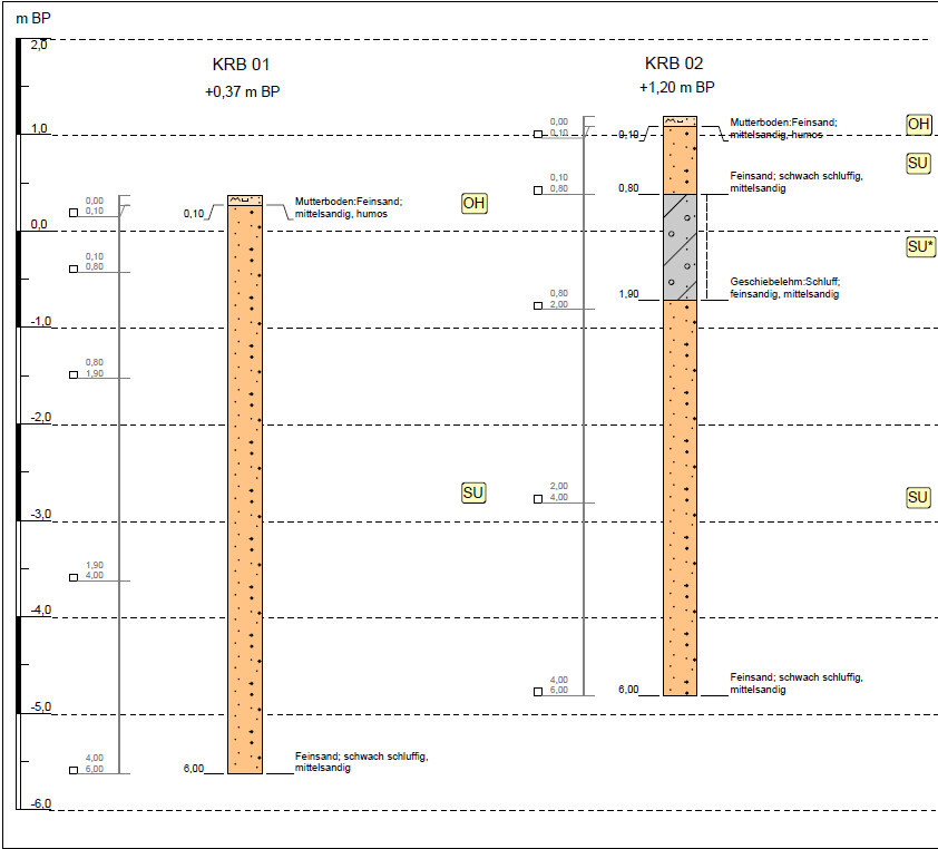
The planned area is located at an elevation between +0.37 m and +1.20 m relative to the reference point. The height difference between the building corners is a maximum of 0.83 m.
A topsoil layer with a thickness of 0.10 m (4 inches) was detected at the surface. The topsoil must be removed and replaced with sufficiently load-bearing fill material. The thicknesses of the topsoil encountered in individual boreholes are listed in Table 1.
Table 1: Topsoil thicknesses from small rotary drilling [m]:
KRB 01: 0.10
KRB 02: 0.10
Below the low-bearing topsoil, slightly silty sand extends down to the final depth of 6.00 m (20 ft) below the NGS, with stiff glacial till clay interspersed between 0.80 m (31 inches) and 1.90 m (75 inches) below NGS in the area of KRB 02. The sequence and thicknesses of the layers are detailed in the borehole profiles (see attachment 1).
No water was found in the open boreholes. Due to the partially fine-grained soils present, groundwater accumulation up to the natural ground surface is expected. The design maximum groundwater level is to be set at the NGS.
4. Soil properties
Based on site inspection and borehole resistance measurements, and considering empirical values, the encountered soils have the following characteristics:
Topsoil (OH):
Shear strength: low
Compressibility: high
Water sensitivity: high
Permeability: moderate
Compaction ability: low
Bearing capacity: low
Slightly silty sand (SU):
Density: predominantly medium dense
Shear strength: medium to high
Compressibility: low
Water sensitivity: medium
Permeability: moderate
Frost susceptibility: F1 to F2
Compaction ability: moderate to good
Bearing capacity: good
Glacial till clay (SU*):
Consistency: predominantly stiff
Shear strength: medium
Compressibility: medium to low
Water sensitivity: high
Permeability: low to moderate
Frost susceptibility: F3
Compaction ability: moderate
Bearing capacity: medium to good
5. Permeability of the subsoil
According to ATV (German regulations for drainage), the relevant infiltration range is between hydraulic conductivity values (kf) of 1 x 10⁻³ and 1 x 10⁻⁶ m/s.
Table 2 provides estimated kf values as an overview.
Table 2: Estimated permeability coefficients kf [m/s] (average and empirical values) for subsoil types:
Soil type / soil group / permeability coefficient [m/s] (estimated)
Slightly silty sand / SU / 5 x 10⁻⁵ to 1 x 10⁻⁶
Glacial till clay, stiff / SU* / 1 x 10⁻⁶ to 1 x 10⁻⁸
The slightly silty sands are classified as moderately to well permeable, and the glacial till clay as moderately to poorly permeable.
For more precise determination of permeability coefficients, open-end tests and/or grain size analyses should be performed.
6. Exposure class determination according to EN 206
The foundation is connected to the natural subsoil or newly introduced fill. Assuming a suitable fill material (e.g., sand without foreign soil or organic components) is used, chemical attack due to elevated sulfate content or acidic soil according to EN 206 is not expected.
Groundwater was not encountered in the foundation area. Therefore, chemical attack on the reinforced concrete foundations from soil or groundwater in accordance with EN 206 is not anticipated.
7. Estimation of soil parameters
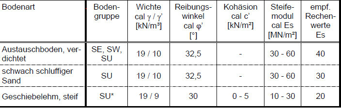
Knowledge of grain size distribution, water content, soil consistency, and density allows conclusions on shear parameters and compressibility of the soil layers, considering empirical values. Based on empirical data for the soils encountered, the soil characteristic values (cal-values) as listed in Table 3 can be applied.
Table 3: Soil characteristic values (average and empirical data)
8. Foundation
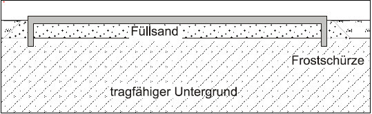
It is assumed that the foundation will be constructed as a reinforced concrete slab with surrounding frost protection skirts and that the bottom edge of the slab will be about +1.20 m above the reference point. The topsoil must be removed and replaced with a well-bearing fill sand.
The soil replacement is to be carried out according to load distribution at a 60° angle beyond the footings. Necessary ground leveling must also be done with well-bearing material.
Figure 1: Example of soil replacement execution with a slab foundation and frost skirts
The fill sand should correspond to soil groups SE, SW, or SU according to DIN 18196 (silt fraction < 10% for particles smaller than 0.063 mm) and be compacted to at least medium density, with D = 0.4 (relative compaction U<3) or D = 0.45 (U>3). Proper execution of the soil replacement must be verified by the construction supervision or geotechnical expert.
During excavation, DIN 4124 (safety requirements when excavating) must be observed. After the subsurface improvement described above, settlements of approximately 0.3 cm (±25%) (at the characteristic point) can be expected for a slab foundation with a uniform load of 25 kN/m².
The average calculated bedding modulus (ksm) for the slab foundation is about 9 MN/m³. If over-reinforcement occurs due to settlement calculations based on these bedding moduli, higher bedding moduli of up to 20 MN/m³ may be used for the elastic bedding of the slab. However, these higher moduli must not be used for settlement calculations.
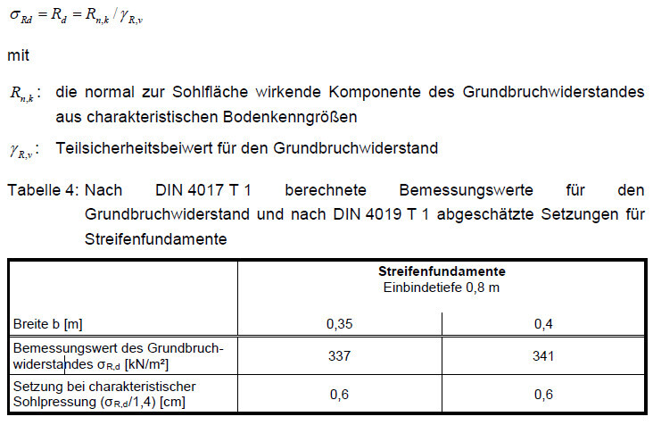
Table 4 below shows the results of earth pressure calculations for strip footings. Settlement calculations and earth pressure analyses were performed to determine the design value for bearing capacity of strip footings. The results can be found in Table 4. The settlements listed result from soil bearing pressures calculated as σRD / 1.4.
The design value for bearing capacity σRd (Rd according to DIN 1054:2010-12) is specified and can be determined from
The building’s waterproofing layer is less than 0.50 m (20 inches) above the design maximum groundwater level. Therefore, waterproofing must be executed according to load case W 2.1-E (Moderate impact from pressurized water with immersion depth less than 3 m) of DIN 18533-1.
For our existing plot of land (389 m² (4,188 sq ft)), we commissioned an elevation plan and a geotechnical report. Unfortunately, I really don’t understand what the geotechnical report says at all.
I have left out some pages, but it’s still quite extensive! Here is an excerpt from the report for which I am hoping to get some help. If anyone could tell me whether the findings indicate a serious problem or if this is fairly standard, or explain how certain conclusions can be drawn, I would be very grateful. I have tried to research this myself online, but without success.
Many thanks in advance for your efforts!!
Construction project: New build of a single-family house without a basement
Soil condition: Topsoil over sand, partially interspersed with glacial till clay
Water table: No water was found in the open boreholes. However, groundwater accumulation up to the level of the natural ground surface (NGS) is to be expected.
Water management: Equipment for open water control should be available
Foundation recommendation: After removing the topsoil, shallow foundation on a load-bearing slab with perimeter strip footings.
Settlements: With shallow foundation, settlement values of 0.3 cm (±25%) for the slab can be expected.
Soil bearing capacity: Individual verifications for 0.35 m and 0.40 m wide strip footings and a load-bearing slab can be found in section 8.
3. Soil profile
The planned area is located at an elevation between +0.37 m and +1.20 m relative to the reference point. The height difference between the building corners is a maximum of 0.83 m.
A topsoil layer with a thickness of 0.10 m (4 inches) was detected at the surface. The topsoil must be removed and replaced with sufficiently load-bearing fill material. The thicknesses of the topsoil encountered in individual boreholes are listed in Table 1.
Table 1: Topsoil thicknesses from small rotary drilling [m]:
KRB 01: 0.10
KRB 02: 0.10
Below the low-bearing topsoil, slightly silty sand extends down to the final depth of 6.00 m (20 ft) below the NGS, with stiff glacial till clay interspersed between 0.80 m (31 inches) and 1.90 m (75 inches) below NGS in the area of KRB 02. The sequence and thicknesses of the layers are detailed in the borehole profiles (see attachment 1).
No water was found in the open boreholes. Due to the partially fine-grained soils present, groundwater accumulation up to the natural ground surface is expected. The design maximum groundwater level is to be set at the NGS.
4. Soil properties
Based on site inspection and borehole resistance measurements, and considering empirical values, the encountered soils have the following characteristics:
Topsoil (OH):
Shear strength: low
Compressibility: high
Water sensitivity: high
Permeability: moderate
Compaction ability: low
Bearing capacity: low
Slightly silty sand (SU):
Density: predominantly medium dense
Shear strength: medium to high
Compressibility: low
Water sensitivity: medium
Permeability: moderate
Frost susceptibility: F1 to F2
Compaction ability: moderate to good
Bearing capacity: good
Glacial till clay (SU*):
Consistency: predominantly stiff
Shear strength: medium
Compressibility: medium to low
Water sensitivity: high
Permeability: low to moderate
Frost susceptibility: F3
Compaction ability: moderate
Bearing capacity: medium to good
5. Permeability of the subsoil
According to ATV (German regulations for drainage), the relevant infiltration range is between hydraulic conductivity values (kf) of 1 x 10⁻³ and 1 x 10⁻⁶ m/s.
Table 2 provides estimated kf values as an overview.
Table 2: Estimated permeability coefficients kf [m/s] (average and empirical values) for subsoil types:
Soil type / soil group / permeability coefficient [m/s] (estimated)
Slightly silty sand / SU / 5 x 10⁻⁵ to 1 x 10⁻⁶
Glacial till clay, stiff / SU* / 1 x 10⁻⁶ to 1 x 10⁻⁸
The slightly silty sands are classified as moderately to well permeable, and the glacial till clay as moderately to poorly permeable.
For more precise determination of permeability coefficients, open-end tests and/or grain size analyses should be performed.
6. Exposure class determination according to EN 206
The foundation is connected to the natural subsoil or newly introduced fill. Assuming a suitable fill material (e.g., sand without foreign soil or organic components) is used, chemical attack due to elevated sulfate content or acidic soil according to EN 206 is not expected.
Groundwater was not encountered in the foundation area. Therefore, chemical attack on the reinforced concrete foundations from soil or groundwater in accordance with EN 206 is not anticipated.
7. Estimation of soil parameters
Knowledge of grain size distribution, water content, soil consistency, and density allows conclusions on shear parameters and compressibility of the soil layers, considering empirical values. Based on empirical data for the soils encountered, the soil characteristic values (cal-values) as listed in Table 3 can be applied.
Table 3: Soil characteristic values (average and empirical data)
8. Foundation
It is assumed that the foundation will be constructed as a reinforced concrete slab with surrounding frost protection skirts and that the bottom edge of the slab will be about +1.20 m above the reference point. The topsoil must be removed and replaced with a well-bearing fill sand.
The soil replacement is to be carried out according to load distribution at a 60° angle beyond the footings. Necessary ground leveling must also be done with well-bearing material.
Figure 1: Example of soil replacement execution with a slab foundation and frost skirts
The fill sand should correspond to soil groups SE, SW, or SU according to DIN 18196 (silt fraction < 10% for particles smaller than 0.063 mm) and be compacted to at least medium density, with D = 0.4 (relative compaction U<3) or D = 0.45 (U>3). Proper execution of the soil replacement must be verified by the construction supervision or geotechnical expert.
During excavation, DIN 4124 (safety requirements when excavating) must be observed. After the subsurface improvement described above, settlements of approximately 0.3 cm (±25%) (at the characteristic point) can be expected for a slab foundation with a uniform load of 25 kN/m².
The average calculated bedding modulus (ksm) for the slab foundation is about 9 MN/m³. If over-reinforcement occurs due to settlement calculations based on these bedding moduli, higher bedding moduli of up to 20 MN/m³ may be used for the elastic bedding of the slab. However, these higher moduli must not be used for settlement calculations.
Table 4 below shows the results of earth pressure calculations for strip footings. Settlement calculations and earth pressure analyses were performed to determine the design value for bearing capacity of strip footings. The results can be found in Table 4. The settlements listed result from soil bearing pressures calculated as σRD / 1.4.
The design value for bearing capacity σRd (Rd according to DIN 1054:2010-12) is specified and can be determined from
The building’s waterproofing layer is less than 0.50 m (20 inches) above the design maximum groundwater level. Therefore, waterproofing must be executed according to load case W 2.1-E (Moderate impact from pressurized water with immersion depth less than 3 m) of DIN 18533-1.
ypg schrieb:
The experts know best – you can’t fully understand or interpret this correctly without any background in geology. A building inspector and/or structural engineer have more knowledge about this. Oh, that’s a pity. I thought someone might be able to draw some conclusions from it.
I just wanted to hear the “bare truth” before anyone tries to sugarcoat it for us.
O
Osnabruecker24 Jun 2020 21:38The report is average.
No construction debris or unusable soil that would need to be removed.
A thin topsoil layer is good, resulting in less fill sand required.
The suggested backfill with sand is more cost-effective than gravel.
Statements about the groundwater level appear in almost every report (the surveyor is playing it safe).
Glacial clay is not ideal beneath the foundation slab but is relatively deep below it. This is acceptable.
(Drillings and opinions in the forum are always just isolated experiences!)
No construction debris or unusable soil that would need to be removed.
A thin topsoil layer is good, resulting in less fill sand required.
The suggested backfill with sand is more cost-effective than gravel.
Statements about the groundwater level appear in almost every report (the surveyor is playing it safe).
Glacial clay is not ideal beneath the foundation slab but is relatively deep below it. This is acceptable.
(Drillings and opinions in the forum are always just isolated experiences!)
I looked into the waterproofing because my general contractor wanted to charge me about €7,500 for a waterproof (WU) foundation slab. However, this was not justified since the report also included an option for W 1.1-E (a normally waterproofed foundation slab).
“The waterproofing layer of the building is located less than 0.50 m (20 inches) above the design flood water level. Therefore, the waterproofing must be carried out according to load case W 2.1-E (moderate exposure to pressurized water with an immersion depth of less than 3 m (10 feet)) as per DIN 18533-1.”
If I understand correctly, W 2.1-E means that you need a waterproof (WU) foundation slab.
“The waterproofing layer of the building is located less than 0.50 m (20 inches) above the design flood water level. Therefore, the waterproofing must be carried out according to load case W 2.1-E (moderate exposure to pressurized water with an immersion depth of less than 3 m (10 feet)) as per DIN 18533-1.”
If I understand correctly, W 2.1-E means that you need a waterproof (WU) foundation slab.
Osnabruecker schrieb:
The report is average.
No construction debris or unusable soil that would need to be removed.
Thin topsoil is good, meaning less fill sand is required.
The suggested filling with sand is cheaper than using crushed stone.
Statements about the water level are almost always included in any report (the surveyor is playing it safe).
Glacial clay is not ideal beneath the house, but it is located relatively far below the foundation slab. It’s acceptable.
(Drillings and opinions in the forum are always just localized experiences!) Thank you very much for your assessment! That doesn’t sound too bad after all.
On one hand, it says that no groundwater was reached down to the drilling depth of 6m (20 feet), and on the other hand, it states that the design highest groundwater level is set at the ground surface level. What should I make of that?
matze07 schrieb:
I had looked into waterproofing because my general contractor wanted to charge me about 7,500 € for a waterproof (WU) concrete slab. But that was unjustified, as the report also included an option for W 1.1-E (a normally waterproofed slab).
“The building’s waterproofing layer is less than 0.50 m (20 inches) above the design highest groundwater level. Therefore, according to loading scenario W 2.1-E (moderate exposure to hydrostatic water pressure with less than 3 m (10 feet) immersion depth) from DIN 18533-1, the waterproofing must be executed accordingly.”
If I am not completely mistaken, W 2.1-E means you need a waterproof (WU) slab. Thank you for the clarification! Shouldn’t the report explicitly state the need for a WU waterproof slab then, or is that something you understand from the corresponding DIN standard based on the W 2.1-E classification?
Similar topics