
ᐅ Planning and Design of a Mechanical Ventilation System with Heat Recovery – Maximum Duct Lengths
Created on: 16 Dec 2018 21:12
C
caddar
Hello everyone,
maybe I don’t actually need to post this question in the telecom-themed forum (and register there as well...).
We are currently planning the (major) renovation of a 1960s house, and the installation of a controlled residential ventilation system is under consideration. While the overall planning is being done by an architect, the ventilation issue has turned out to be a bit more complicated. The HVAC company has the ventilation system planned by a wholesaler (it concerns a Pichler LG350), and communication has been difficult there (openings face the neighboring terraced house, etc.).
Before we either fire the company or ditch the ventilation system altogether (or just have the HVAC contractor handle heating and plumbing), I wanted to clarify a fundamental point here:
- In the "ventilation plan" (created using a variant of airPLAN software, which apparently circulates in various freeware versions) it says: Maximum length between manifold and supply diffuser: 15 m (50 feet).
Question: Does anyone know if this is correct? Is this completely independent of the device? This number also appeared in my "test draft," which I created with the above-mentioned software entirely without devices.
With a potentially "old-building-compliant" installation in the attic (and corresponding ductwork), we would definitely exceed the 15 m (50 feet) duct length.
At the moment, we are leaning towards giving up on the system and ventilating minimally with decentralized units (e.g., in utility rooms)...
Christoph
maybe I don’t actually need to post this question in the telecom-themed forum (and register there as well...).
We are currently planning the (major) renovation of a 1960s house, and the installation of a controlled residential ventilation system is under consideration. While the overall planning is being done by an architect, the ventilation issue has turned out to be a bit more complicated. The HVAC company has the ventilation system planned by a wholesaler (it concerns a Pichler LG350), and communication has been difficult there (openings face the neighboring terraced house, etc.).
Before we either fire the company or ditch the ventilation system altogether (or just have the HVAC contractor handle heating and plumbing), I wanted to clarify a fundamental point here:
- In the "ventilation plan" (created using a variant of airPLAN software, which apparently circulates in various freeware versions) it says: Maximum length between manifold and supply diffuser: 15 m (50 feet).
Question: Does anyone know if this is correct? Is this completely independent of the device? This number also appeared in my "test draft," which I created with the above-mentioned software entirely without devices.
With a potentially "old-building-compliant" installation in the attic (and corresponding ductwork), we would definitely exceed the 15 m (50 feet) duct length.
At the moment, we are leaning towards giving up on the system and ventilating minimally with decentralized units (e.g., in utility rooms)...
Christoph
Somewhere the unit has to be installed; it can either lie flat or be mounted on a wall. However, this takes up a lot of space along your pipes leading to the exterior wall.
Then, a separate duct runs to each room, which can have a rectangular cross-section of about 5cm x 10cm (2 inches x 4 inches).
If you chisel out the ceiling in the central hallway to make room for four ducts, you could hang the unit from the basement ceiling.
At least, I don’t see a problem with the 15 meters (49 feet).
Otherwise, a decentralized system, but I am not familiar with that.
Then, a separate duct runs to each room, which can have a rectangular cross-section of about 5cm x 10cm (2 inches x 4 inches).
If you chisel out the ceiling in the central hallway to make room for four ducts, you could hang the unit from the basement ceiling.
At least, I don’t see a problem with the 15 meters (49 feet).
Otherwise, a decentralized system, but I am not familiar with that.
Attached are the floor plans. The dashed lines are usually remnants of the "demolition lines," which I tried to remove quickly for better clarity.
On the ground floor, there is a suspended ceiling in the kitchen area and a large built-in unit around the installation shaft, making these ideal locations to install the valves.
The marked positions have not yet been planned by a professional (please don’t stone me!), but I tried to allocate them based on the number and routing plan.
We are now considering whether the effort is really worth it, or if we should just install a few targeted fans in the bathrooms/WC and leave the rest “traditional.” It will be a KfW70 house, meaning energetically we can easily afford that without any funding issues.
From top (attic) to bottom (ground floor)
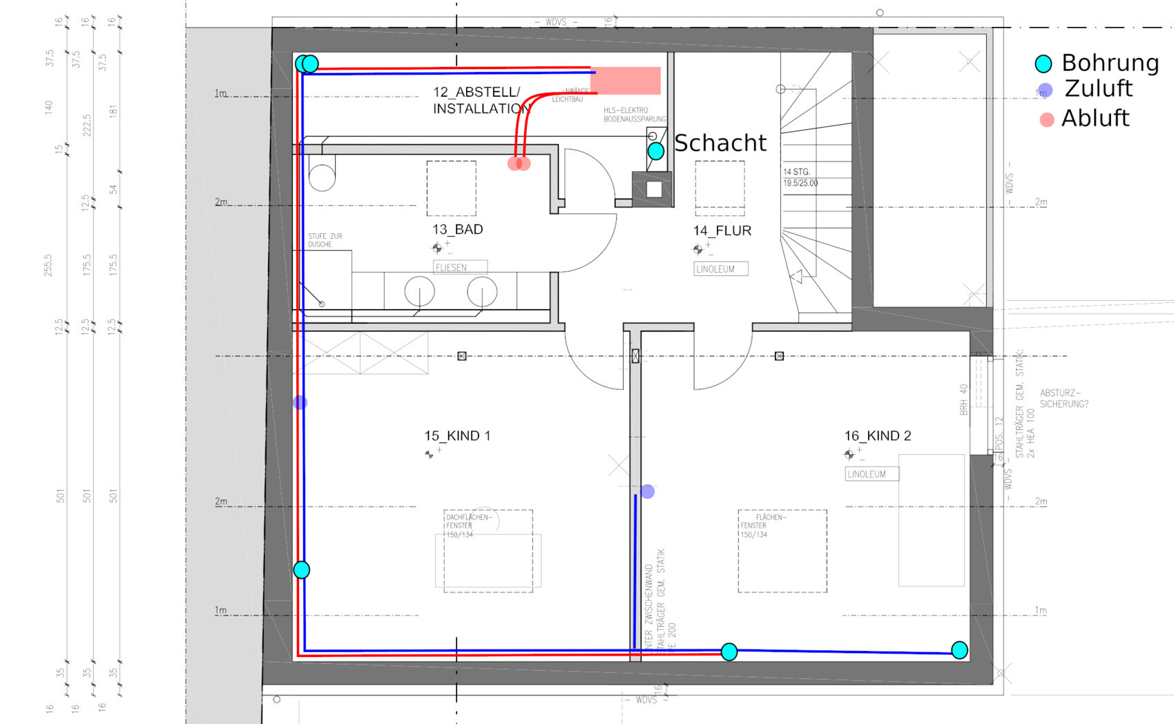

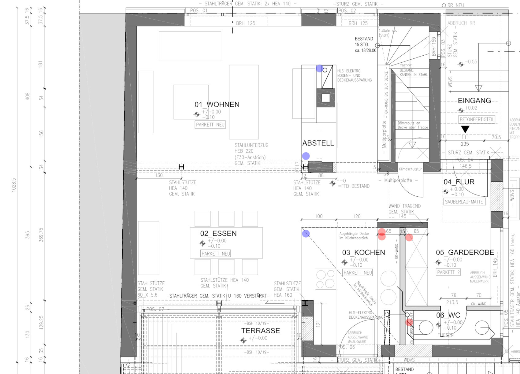
On the ground floor, there is a suspended ceiling in the kitchen area and a large built-in unit around the installation shaft, making these ideal locations to install the valves.
The marked positions have not yet been planned by a professional (please don’t stone me!), but I tried to allocate them based on the number and routing plan.
We are now considering whether the effort is really worth it, or if we should just install a few targeted fans in the bathrooms/WC and leave the rest “traditional.” It will be a KfW70 house, meaning energetically we can easily afford that without any funding issues.
From top (attic) to bottom (ground floor)

Without having thought it through in too much detail:
You could create a shaft below the chimney and run two large riser ducts through the floors there.
Ground floor: Lower the ceiling in the hallway in front of the staircase down to the kitchen, where the exhaust air will be directed. Supply air can simply be blown straight left into the living room.
Upper floor: Lower the ceiling in the stairwell hallway, direct the exhaust air straight left into the bathroom, supply air goes into a small distributor in the hallway, from there downwards into children's room 2 and then through the wall into children's room 1. In children's room 2, create a boxed-in area under the ceiling in the corner. This could, for example, run along the entire wall height and be turned into a built-in shelf below the covered ducting, making it look intentional ;-)
Edit: Of course, the supply air could also simply be blown from the hallway over the doors into the rooms...
Attic: Lower the ceiling in the hallway area. Exhaust air straight down into the bathroom, supply air distributor under the hallway ceiling and from there over the doors into the three rooms.
Overall effort: 6 core drills through the ceilings, lowering the ceiling in the hallway 3 times, cladding 2 riser shafts in the hallway, all ductwork less than 5m (16 feet) long.
You could create a shaft below the chimney and run two large riser ducts through the floors there.
Ground floor: Lower the ceiling in the hallway in front of the staircase down to the kitchen, where the exhaust air will be directed. Supply air can simply be blown straight left into the living room.
Upper floor: Lower the ceiling in the stairwell hallway, direct the exhaust air straight left into the bathroom, supply air goes into a small distributor in the hallway, from there downwards into children's room 2 and then through the wall into children's room 1. In children's room 2, create a boxed-in area under the ceiling in the corner. This could, for example, run along the entire wall height and be turned into a built-in shelf below the covered ducting, making it look intentional ;-)
Edit: Of course, the supply air could also simply be blown from the hallway over the doors into the rooms...
Attic: Lower the ceiling in the hallway area. Exhaust air straight down into the bathroom, supply air distributor under the hallway ceiling and from there over the doors into the three rooms.
Overall effort: 6 core drills through the ceilings, lowering the ceiling in the hallway 3 times, cladding 2 riser shafts in the hallway, all ductwork less than 5m (16 feet) long.
Dr Hix schrieb:
Without thinking about it too much:
You could create a shaft below the chimney and run two thick riser pipes through the floors there.Thank you very much for the contribution; that might be a viable option. The problem here is a large concrete beam cutting through the hallway on the ground floor (by the way, the plan is oriented north, which I forgot to mark). This means it would be more difficult to route the pipes from the chimney in the north towards the kitchen without reducing the hallway ceiling height to about 2.1m (7 feet) in the area of the lintel. If I suggest drilling holes to the structural engineer, I’ll probably get in serious trouble for compromising the structure. ;-)
We will discuss this again with all parties involved and might decide to forgo the installation. Or we might find a solution similar to the one Dr Hix proposed. I’ll hopefully provide an update here later (if I remember) for those who come across this thread in the future.
Thanks!
Similar topics