
ᐅ Equipotential bonding for satellite systems must be installed separately.
Created on: 3 Oct 2017 01:16
R
Redsonic
Hello everyone,
My home savings contract pointed out during our new build that the equipotential bonding for the grounding of the satellite system must not be installed together with the other electrical wiring. The green-yellow conductor is now running through our bathroom bundled in a large cable harness all the way down.
What do you think: Does the grounding conductor for the satellite system need to be installed separately? I informed the electrician, but nothing was done. Now time is pressing a bit, as the plumbing crew is preparing the floor for the underfloor heating and the cables will soon be covered.
Good luck, Redsonic
My home savings contract pointed out during our new build that the equipotential bonding for the grounding of the satellite system must not be installed together with the other electrical wiring. The green-yellow conductor is now running through our bathroom bundled in a large cable harness all the way down.
What do you think: Does the grounding conductor for the satellite system need to be installed separately? I informed the electrician, but nothing was done. Now time is pressing a bit, as the plumbing crew is preparing the floor for the underfloor heating and the cables will soon be covered.
Good luck, Redsonic
W
winnetou7810 Oct 2017 17:11winnetou78 schrieb:
I'll join in here.
Since I'm installing the satellite system myself,
how exactly should I proceed?
The electrician will run the connections and cables up to the attic.
I plan to mount the satellite system on the rafter brackets, connect the LNB with four cables, and attach them to a grounding block in the attic.
From there, the electrician would continue running the cables later.
That should be correct, I think.
But now about the equipotential bonding.
Should I run a 16mm (0.63 inch) copper conductor individually from the satellite to the utility room, and from the grounding block run a copper conductor to the satellite dish?
Is that the correct way?
How exactly do I fasten the copper conductor to the mast?
With a clamp?What do you think about this?
Thanks for your help,
winnetou78 schrieb:
The electrician will run the connections and cables up to the attic.
I wanted to install the satellite system on the rafter bracket, bring in four cables from the LNB, and attach them to a grounding block in the attic.
From there, the cables would later be routed further by the electrician. No one emphasizes more often than I do that according to NAV § 13, installations of grounding and equipotential bonding must be carried out by licensed electricians.
Considering that only a few antennas installed by electricians are fully compliant with standards, this can also be challenging.
winnetou78 schrieb:
But now the equipotential bonding.
Run 16mm² (AWG 5) copper wire from the satellite system to the utility room separately, and from the grounding block a copper cable to the satellite dish?
Is that correct? Yes, that would be a code-compliant grounding, provided that, exceptionally, the connections to the rafter bracket and the grounding system are certified to withstand lightning currents of 100 kA. A 16mm² (AWG 5) copper conductor can withstand, with suitable terminals, extremely high lightning currents up to 200 kA.
winnetou78 schrieb:
How exactly do I attach the copper wire to the mast?
Clamp? Actually, you should not do that yourself, since you are not a licensed electrician, see above.
- Grounding conductors must be connected at masts or vertical pipes of rafter brackets with lightning current resistant grounding clamps certified to class H. So far, there is no rafter bracket with a certified terminal for grounding conductors.
- If the grounding conductor is connected at the main grounding terminal (MGT), it must be designed for lightning equipotential bonding, and not just a common busbar for power equipotential bonding according to standards such as VDE 0100 series.
- The equipotential bonding of cable shields is connected via grounding blocks or grounding angles and with non-lightning-resistant 4mm² (AWG 12) copper wire to the grounded system, as are the housings of mains-powered components, in particular multiswitches (even if located in the basement).
- For this, standard band grounding clamps with an M6 screw and saddle are sufficient; a properly applied cable lug on an M5 screw also works.
Pictures say more than words. Unfortunately, the system currently shows that I do not have permission to upload them.
W
winnetou7810 Oct 2017 18:16Too bad, but thanks anyway.
P.S. Sometimes it’s better when a layperson does it after a lot of reading and asking about standards or codes, rather than a so-called qualified electrician who does it the way they always have.
I asked two electricians, and both said, just install the satellite dish and that’s it [emoji45]
P.S. Sometimes it’s better when a layperson does it after a lot of reading and asking about standards or codes, rather than a so-called qualified electrician who does it the way they always have.
I asked two electricians, and both said, just install the satellite dish and that’s it [emoji45]
winnetou78 schrieb:
I asked two electricians, and both said just install the satellite and that's it [emoji45] You are not the first layperson to contact the forum seeking advice on grounding and equipotential bonding who is more knowledgeable about standards than some electricians.
If the announced revision of IEC 60728-11 goes through as I expect, it won’t make any difference to those two non-certified electrical "professionals" since they won’t be aware of the changes.
W
winnetou7810 Oct 2017 19:22I agree. But this happens in many areas; just take the leveling layer as an example. I have looked at at least 30 concrete slabs over the past six months, and all of them had dimpled membrane underneath.
Since I happened to come across the old thread, here is a follow-up example image from the currently valid DIN EN IEC 60728-11 (VDE 0855-1):2023-10:
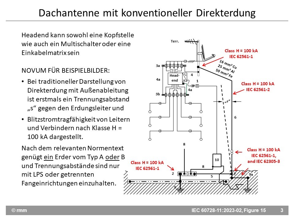
Grounding conductors made of 16 mm² (0.025 in²) copper, 25 mm² (0.04 in²) aluminum, or 50 mm² (0.08 in²) steel can withstand even rare lightning strikes exceeding 200 kA. However, every chain is only as strong as its weakest link, which is why antenna grounding can only fulfill its intended lightning protection function if the connectors used with the respective grounding conductors are certified according to the highest test class H with 100 kA.
The requirement that accessible grounding conductors must be installed inside a PVC conduit with a 3 mm (0.12 in) wall thickness has been removed.
Grounding conductors made of 16 mm² (0.025 in²) copper, 25 mm² (0.04 in²) aluminum, or 50 mm² (0.08 in²) steel can withstand even rare lightning strikes exceeding 200 kA. However, every chain is only as strong as its weakest link, which is why antenna grounding can only fulfill its intended lightning protection function if the connectors used with the respective grounding conductors are certified according to the highest test class H with 100 kA.
The requirement that accessible grounding conductors must be installed inside a PVC conduit with a 3 mm (0.12 in) wall thickness has been removed.
Similar topics