ᐅ Multiswitch for Satellite TV: Install in the Attic or Basement?
Created on: 31 May 2016 19:34
W
world-e
Hello everyone,
What are your thoughts on the best location for installing the satellite multiswitch? Does it make more sense to place it in the unheated attic space or in the technical room in the basement?
The house will have two full floors with a shallow pitched roof (unheated attic) and a basement.
Advantages of the attic:
- Less signal loss, since the multiswitch is close to the satellite dish
- Less cabling effort, as most connections are on the upper floor (3x twin outlets). This allows the rooms to be connected directly. Ground floor (2x twin), basement (1x twin)
- Satellite cables between the multiswitch and the satellite dish are easier to replace if they fail after several years
Advantages of the basement:
- Fewer penetrations through the vapor barrier in the top floor ceiling
- All technical equipment is located in the basement technical room
Thank you for your opinions and suggestions.
Uwe82 schrieb:
Be careful with cable connections: the cables are only allowed to have 95 dB shielding effectiveness, otherwise the technician is not allowed to connect them. We installed 120 dB.This is complete nonsense!Cable network operators prefer triple-shielded cables with shielding attenuation and coupling resistance rated honestly as Class A+, but they also accept existing cables with double shielding made of solid copper and proven Class A quality. The values should always be better if possible. 100 dB shielding attenuation is technically achievable without problems even with double shielding. Class A already reduces emitted interference and system emissions to harmless, minimal levels, so more is not necessary.
4- and 5-layer shielding only makes installation and connector assembly more difficult. Such cables are often used to impress uninformed consumers together with misleading peak shielding attenuation values (individual peak outliers). Honest and serious marketing, like regarding the physically impossible noise figure specifications of LNBs, generates less sales because many customers want to be deceived as long as it’s cheap.
The worse a cable is, the louder the advertising with claims like HD-capable etc. If a cable network operator has rejected a cable, it was not due to too high shielding attenuation, but because it
- has a braid made of fragile aluminum that is prone to breakage and poor modulation performance,
- features excessive and ineffective multiple shielding layers,
- has poor coupling resistance,
According to the current DIN 18015 standard, multiswitches should be installed in central communication distribution units and from there, all information and communication technology (ICT) and radio and communication lines should be distributed in a star topology.
This usually requires installation in the basement.
This usually requires installation in the basement.
Hey Dipol, if the multiswitch is supposed to be installed in the (not just a) central communication distribution box, how do you implement the equipotential bonding for that distributor?
The multiswitch can only be grounded via the mast (without creating loops). A communication distribution box also needs to be connected to the equipotential bonding, so wouldn’t that setup no longer be loop-free?
What is the solution:
a) Also ground the communication distribution box exclusively through the mast
b) Install the multiswitch isolated within the central communication distribution box and ground it separately
c) Something completely different (feel free to explain in detail)
??
B
Bieber08151 Jun 2016 22:06Dipol schrieb:
According to the current DIN 18015 standard, multiswitches should be installed in central communication distribution cabinets and all information and communication (I&C) as well as radio and communication (R&C) cables should be distributed in a star topology from there.
This usually requires installation in the basement. Is this conclusion really mandatory? Why couldn’t a central communication distribution cabinet also be located in the attic?
This concerns me because I am buying a house with satellite wiring from the developer. I would like to know where the multiswitch should or may be installed.
Bieber0815 schrieb:
Is this conclusion really necessary? Why couldn’t a central communication distribution point also be located in the attic?"Mostly" does not mean "necessarily." Furthermore, the DIN 18015 standard can be contractually excluded.
Bieber0815 schrieb:
I am affected because I’m buying a house with satellite cabling from the developer. I would like to know where the multiswitch should or is allowed to be installed.I strongly doubt that the conditions in an uninsulated attic are suitable for a multiswitch. It simply gets too hot there.
[QUOTE="SirSydom, post: 135967, member: 21891"]
What is the solution:
a) Ground communication distributors exclusively via the mast as well
b) Build the multiswitch isolated in the central communication distributor and ground separately
c) something different (detailed suggestions welcome)
??
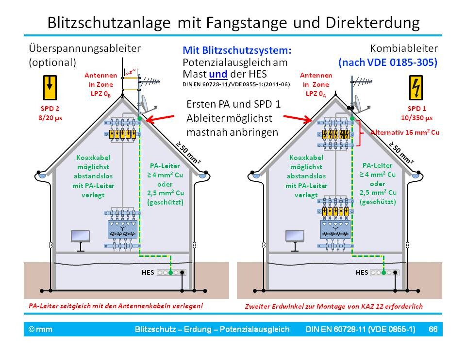
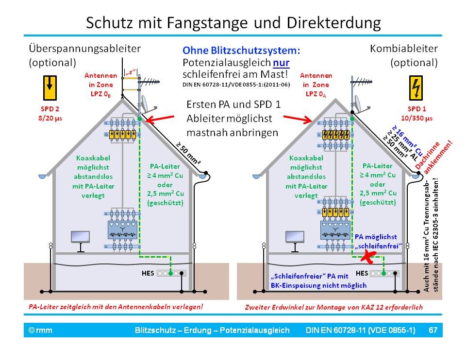
Only a few readers will know that this primarily concerns the concept of loop-free grounding, which according to IEC 60728-11 is required for protective equipotential bonding (PEB) of conventionally directly grounded antennas. For easier understanding, here is a basic list ranked by priority:
The primary standard for antenna safety, IEC 60728-11, has not yet fully adapted to the multimedia world and the convergence of different media, unlike the other IEC 60728-x sub-standards.
Considering all factors, when combining grounding-required rooftop antennas with cable TV or telephone networks, the loop-free equipotential bonding of the rooftop antenna inevitably cannot be maintained. Therefore, the equipotential bonding of antenna cables must necessarily be connected not only at the grounded antenna carrier—as is already the case for direct grounding in lightning protection systems—but also at the main equipotential bonding bar, which unavoidably introduces loops.
The internal standard discrepancy in IEC 60728-11 does not apply in cases of
Direct grounding in the event of lightning strikes inevitably results in partial lightning current coupling into the antenna system and connected devices. Therefore, while this protective method still complies with the recognized rules of technology (= minimum standard), it no longer meets the current state of the art.
Pictures are worth a thousand words. To deepen understanding, here are two slides illustrating rooftop antennas with and without lightning protection systems, and with and without separate air-termination systems.
What is the solution:
a) Ground communication distributors exclusively via the mast as well
b) Build the multiswitch isolated in the central communication distributor and ground separately
c) something different (detailed suggestions welcome)
??
Only a few readers will know that this primarily concerns the concept of loop-free grounding, which according to IEC 60728-11 is required for protective equipotential bonding (PEB) of conventionally directly grounded antennas. For easier understanding, here is a basic list ranked by priority:
- Ideally, all supply and communication cables should enter the building at a single point—LEUTRON coined the term Single-Entry-Point principle for this
- Loops should be avoided to minimize inductive coupling of lightning currents
- The shields of all cables and lines entering or exiting the building from Lightning Protection Zone (LPZ) 0A must always be included in the equipotential bonding (PEB) as close as possible to the building entry point.
- Therefore, the shields of underground cables for cable TV and landline telephone networks must be connected to the main equipotential bonding bar (MEB) over the shortest possible path—there is no alternative here.
- Cable shields of optimally directly grounded rooftop antennas, on the other hand, should generally be bonded loop-free close to the mast/antenna carrier, which is grounded to withstand lightning current. In exceptional cases, where the grounding is routed further down and deeper into the building, the PEB must be connected there.
The primary standard for antenna safety, IEC 60728-11, has not yet fully adapted to the multimedia world and the convergence of different media, unlike the other IEC 60728-x sub-standards.
Considering all factors, when combining grounding-required rooftop antennas with cable TV or telephone networks, the loop-free equipotential bonding of the rooftop antenna inevitably cannot be maintained. Therefore, the equipotential bonding of antenna cables must necessarily be connected not only at the grounded antenna carrier—as is already the case for direct grounding in lightning protection systems—but also at the main equipotential bonding bar, which unavoidably introduces loops.
The internal standard discrepancy in IEC 60728-11 does not apply in cases of
- Direct grounding via a lightning protection system
- Antenna installation in LPZ 0B (Lightning Protection Zone 0B) with separate air-termination systems
- Antenna installation on façade areas not requiring grounding
Direct grounding in the event of lightning strikes inevitably results in partial lightning current coupling into the antenna system and connected devices. Therefore, while this protective method still complies with the recognized rules of technology (= minimum standard), it no longer meets the current state of the art.
Pictures are worth a thousand words. To deepen understanding, here are two slides illustrating rooftop antennas with and without lightning protection systems, and with and without separate air-termination systems.
Similar topics