
ᐅ Challenges for MEP planners: underfloor heating flow temperature and wastewater ventilation
Created on: 15 Jul 2022 10:22
P
Pacmansh
Hello,
we are at the beginning of the construction phase for our development project with the builder, and I am having some disagreements with the MEP planner. To be better prepared for the discussion, I would appreciate your assessment.
Point 1) Supply temperature of underfloor heating, new building, KfW55 standard, air-to-water heat pump
The supply temperature of the underfloor heating (end-terrace house on both floors) was stated to me as 40°C (104°F) after inquiry. This seems absurdly high to me. Additionally, I was informed that the surface temperature is designed to a maximum of 27°C (81°F) due to the flooring materials. Somehow, this does not seem consistent. When I asked about lowering the supply temperature, the response was: "A general reduction is not feasible with the underfloor heating without reducing the pipe spacing to an unacceptable level."
Do you have any ideas how I can respond to this in a reasonably professional way? Are there any documents or sources I could refer to, or information I should request?
Point 2) Wastewater venting
Contrary to earlier agreements, this has been planned in a rather unfavorable location. The reason given is "because the wastewater vent and the residential ventilation (exhaust air) must be routed over the roof with a certain separation according to flat roof guidelines." What distance should be maintained here? A quick online search only showed a 30cm (12 inches) distance to other building components. Basically, this is about the roof penetrations and their distance from each other, correct?
we are at the beginning of the construction phase for our development project with the builder, and I am having some disagreements with the MEP planner. To be better prepared for the discussion, I would appreciate your assessment.
Point 1) Supply temperature of underfloor heating, new building, KfW55 standard, air-to-water heat pump
The supply temperature of the underfloor heating (end-terrace house on both floors) was stated to me as 40°C (104°F) after inquiry. This seems absurdly high to me. Additionally, I was informed that the surface temperature is designed to a maximum of 27°C (81°F) due to the flooring materials. Somehow, this does not seem consistent. When I asked about lowering the supply temperature, the response was: "A general reduction is not feasible with the underfloor heating without reducing the pipe spacing to an unacceptable level."
Do you have any ideas how I can respond to this in a reasonably professional way? Are there any documents or sources I could refer to, or information I should request?
Point 2) Wastewater venting
Contrary to earlier agreements, this has been planned in a rather unfavorable location. The reason given is "because the wastewater vent and the residential ventilation (exhaust air) must be routed over the roof with a certain separation according to flat roof guidelines." What distance should be maintained here? A quick online search only showed a 30cm (12 inches) distance to other building components. Basically, this is about the roof penetrations and their distance from each other, correct?
So, after a lot of emails and phone calls, I have at least received the heating design based on a 40°C (104°F) supply temperature. They are not willing to share the current plan with a 38°C (100°F) supply temperature. However, I have managed to arrange a meeting where they will present the current 38°C (100°F) supply plan.
Maybe you could still lend me a hand and help me understand the 40°C plan or give advice on what else I should be paying attention to. Below, I have attached the table with the design details. I added the last row with the heating load for the supply air, calculated by me (air volume flow * specific heat capacity of air * temperature difference at -16°C (3°F) outdoor temperature). I have also attached the floor plans. My goal right now is to be well prepared for the meeting on Monday, so I can spot if anything is obviously planned incorrectly. Many thanks in advance!
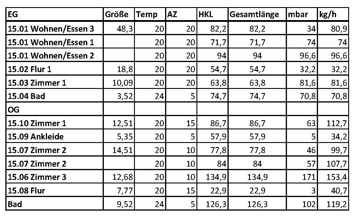
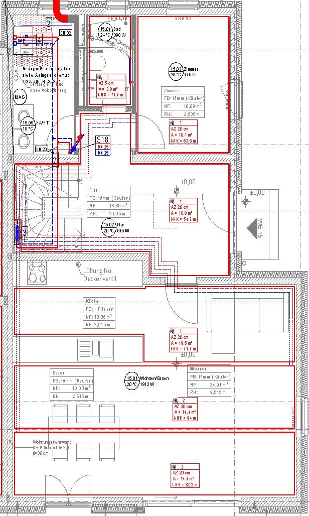
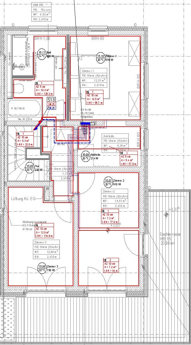
Maybe you could still lend me a hand and help me understand the 40°C plan or give advice on what else I should be paying attention to. Below, I have attached the table with the design details. I added the last row with the heating load for the supply air, calculated by me (air volume flow * specific heat capacity of air * temperature difference at -16°C (3°F) outdoor temperature). I have also attached the floor plans. My goal right now is to be well prepared for the meeting on Monday, so I can spot if anything is obviously planned incorrectly. Many thanks in advance!
S
stjoob_at6 Oct 2022 11:53Circuit lengths vary quite a bit. This is not ideal for the hydraulic balancing.
As a quick solution, you could combine the hallway and dressing room on the upper floor (80.8 m² (869 sq ft)) and split Bedroom 3 and the bathroom into two circuits (67.45 m² (726 sq ft) and 63.15 m² (680 sq ft), respectively).
Is it not possible to have wall heating in the bathroom?
As a quick solution, you could combine the hallway and dressing room on the upper floor (80.8 m² (869 sq ft)) and split Bedroom 3 and the bathroom into two circuits (67.45 m² (726 sq ft) and 63.15 m² (680 sq ft), respectively).
Is it not possible to have wall heating in the bathroom?
R
RotorMotor6 Oct 2022 11:58Is there anything different now? It seems to me that we have already discussed all of this.
stjoob_at schrieb:
Is it not possible to have wall heating in the bathroom? I think that is very difficult to implement under the current arrangement of the developer/planner/general contractor/subcontractors.
RotorMotor schrieb:
Is anything different now? It looks to me like we’ve already discussed all of this? You’re right, we have discussed it. I just wanted to finally provide some data and sorry, I just noticed the table was cut off. Attached is the complete table.
Questions that immediately come to mind:
- Does the flooring have an impact on the required heat load? I assume the HVAC planner calculated with parquet flooring, but we are installing glued vinyl.
- The standard heat load should already include the additional required heat load, correct? For example, Room 15.01 has a heat load of 1912 W, of which 490 W are used for heating the supply air, right?
- What exactly does the column “mbar” indicate?
R
RotorMotor6 Oct 2022 15:16Pacmansh schrieb:
You’re right, we already discussed this. I just wanted to finally provide the data, and sorry, I just noticed the table was cut off. Attached is the complete table. Ah, now also with heating loads. 😉
Pacmansh schrieb:
- Does the floor covering affect the required heating load? I assume the building services engineer planned with hardwood flooring, but we’re installing glued vinyl. The floor covering does not affect the heating load.
The load is only what causes heat losses.
However, it does make a difference on the generation side. Glued vinyl is more comparable to tiles.
Pacmansh schrieb:
- The standard heating load should already include the additional necessary heating load, right? For example, room 15.01 has a heating load of 1912 W, and 490 W of this is used for heating the supply air, correct? That’s a good question. I suspect you have to add them together.
In my opinion, it’s incorrect to assume the bathrooms have no ventilation loss.
After all, air that is four degrees Celsius (7°F) colder continuously flows into the bathrooms.
Pacmansh schrieb:
- What exactly does the "mbar" column indicate? That shows the pressure loss.
S
stjoob_at6 Oct 2022 15:39Standard heating load usually includes everything (transmission heat losses + ventilation heat losses).
In your case, it would be 7 kW, which is quite high for a new build.
The last column is unclear. Does it represent the ventilation heat losses (which doesn’t make much sense since some rooms are missing) or the exchange between rooms (the hallway is missing as well)?
In your case, it would be 7 kW, which is quite high for a new build.
The last column is unclear. Does it represent the ventilation heat losses (which doesn’t make much sense since some rooms are missing) or the exchange between rooms (the hallway is missing as well)?
Similar topics