ᐅ Underfloor heating with an air-to-water heat pump. House gets too warm when the sun is shining.
Created on: 4 Dec 2019 14:18
C
chewbacca123
Hello everyone,
I have a general question.
We moved into our new build four months ago. The living area on the ground floor has three large floor-to-ceiling windows facing south. We have underfloor heating and an air-to-water heat pump.
It provides a really comfortable temperature inside the house, but we have a problem – whenever the sun is shining in winter, even if it’s -2°C (28°F) outside, the temperature suddenly rises to 24°C (75°F) in the living room. It gets uncomfortably warm in here, and the underfloor heating can’t be turned down quickly.
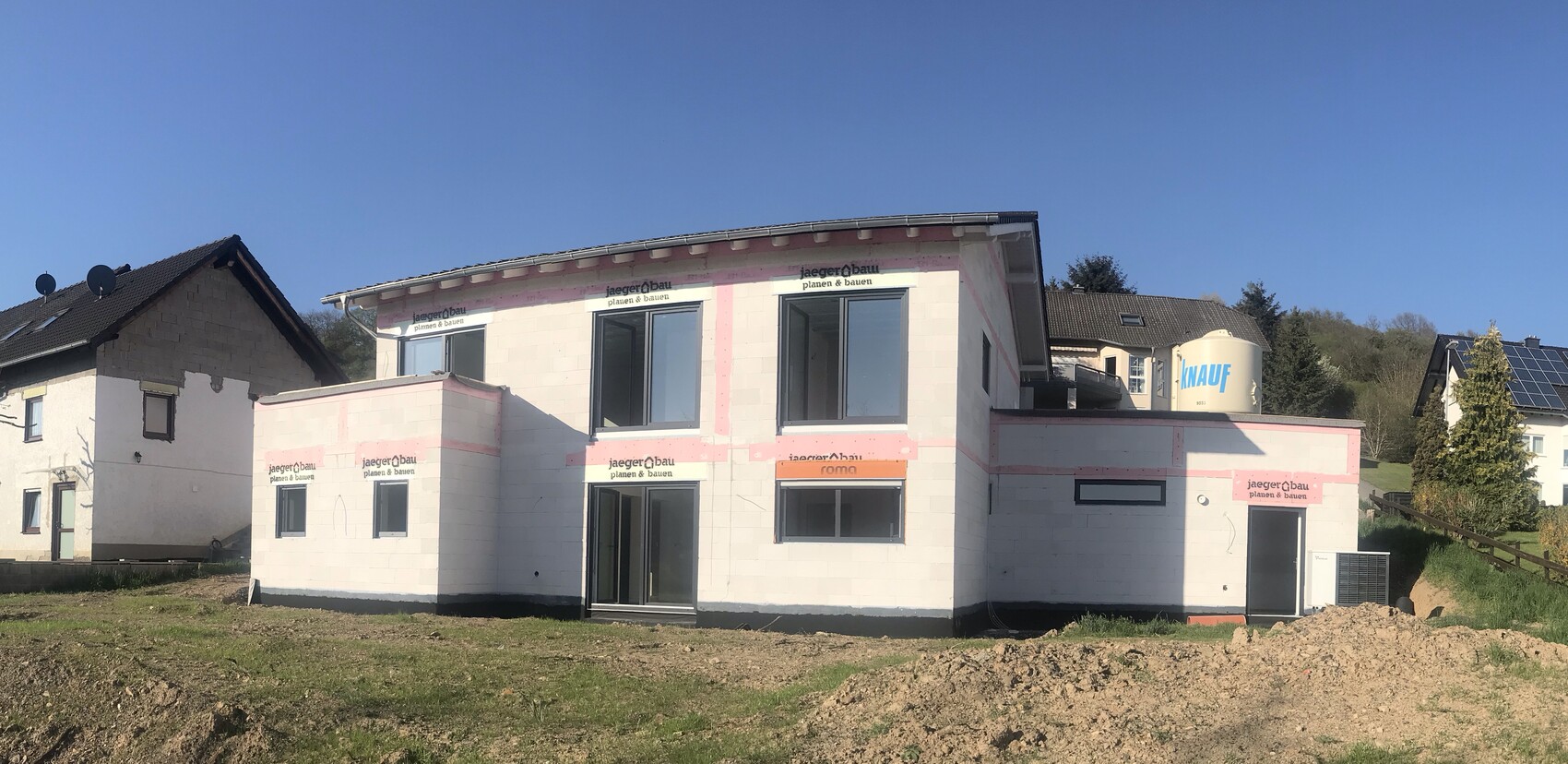
Should we assume that the large floor-to-ceiling windows are responsible for the heat gain? A photo of the south-facing side of the house is attached.
What would you do – always lower all the blinds as soon as sunlight is forecast? That seems quite annoying...
We have motorized blinds controlled by Somfy. Would you consider buying a sensor that automatically lowers the blinds at a certain temperature?
Thanks in advance for your replies.
I have a general question.
We moved into our new build four months ago. The living area on the ground floor has three large floor-to-ceiling windows facing south. We have underfloor heating and an air-to-water heat pump.
It provides a really comfortable temperature inside the house, but we have a problem – whenever the sun is shining in winter, even if it’s -2°C (28°F) outside, the temperature suddenly rises to 24°C (75°F) in the living room. It gets uncomfortably warm in here, and the underfloor heating can’t be turned down quickly.
Should we assume that the large floor-to-ceiling windows are responsible for the heat gain? A photo of the south-facing side of the house is attached.
What would you do – always lower all the blinds as soon as sunlight is forecast? That seems quite annoying...
We have motorized blinds controlled by Somfy. Would you consider buying a sensor that automatically lowers the blinds at a certain temperature?
Thanks in advance for your replies.
D
Daniel-Sp13 Dec 2019 20:58LAD 9 or LADV 9?
Unfortunately, LAD 9 does not mean performance-controlled.
How many square meters do you have? What energy standard, energy saving regulation, or KfW level?
LAD 9 also means
Minimum volume flow 1600 l/h (43 gallons per hour), nominal volume flow 2000 l/h (53 gallons per hour). That’s quite a statement... but it’s no use, you have to deal with it. Looking at your two CSV files, you still have around 30 compressor starts per day. That is way too many.
But first, finish the list and then we’ll see how to proceed.
However, I’m afraid maintaining 24°C (75°F) in the bathroom won’t be achievable...
I’ll get back to you as soon as you’ve compiled the data. The tubes usually show l/min (liters per minute). Ideally, you should aim for around 27 l/min (0.95 gallons per minute).
Regards, Daniel
 chewbacca12314 Dec 2019 10:24
Daniel-Sp schrieb:
LAD 9 Hello Daniel, I have created the table, and the flow rates in liters per minute (l/min) should be roughly correct (l/min is the value reached at the end of the red tip of the float, right?). What is definitely too high is the value for the small bathroom on the ground floor, since we don’t need that much heating capacity there—the bathroom is very small. The dressing room in the basement also doesn’t need 2.5 l/min, more like 1.
The main bathroom in the basement needs more, and I would say the hallways need a bit more flow as well.
D
Daniel-Sp14 Dec 2019 11:10You should reconsider the desired temperatures. Having 18°C (64°F) in the hallway and a 4-5°C (7-9°F) difference in the adjacent bathroom will not work. Maybe a 2°C (4°F) difference with closed doors. Keep in mind that the bathroom transfers heat to the hallway, and the greater the difference, the more heat is transferred.
There must not be any rooms with zero air flow. You need the volume flow!
There must not be any rooms with zero air flow. You need the volume flow!
D
Daniel-Sp14 Dec 2019 12:04Have you now removed the actuators?
chewbacca12314 Dec 2019 13:35Daniel-Sp schrieb:
Did you remove the actuators now?What exactly are actuators? Yes, about the temperatures, that was just a rough estimate – of course, it's adjustable in other ways as well. I have now set all the individual room controllers to full output. Now I’m checking below the heat pump; it has been off for 2 hours. It hasn’t done that for a long time, it usually switches on all the time. That’s a good sign, so it doesn’t seem to be getting too hot anywhere so far.
D
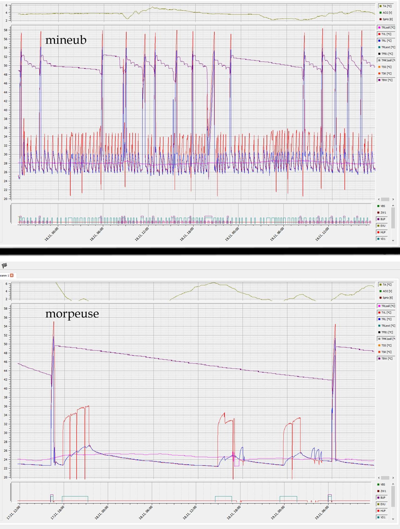
Daniel-Sp14 Dec 2019 14:00Actuators are the white parts on top of the heating circuit distributor. It’s better to remove them. Otherwise, they might unexpectedly shut off the heating circuit. You need a continuous flow in the heating circuits for the heat pump. You set the room temperature once by adjusting the flow rate, and that setting stays for good. With ERR, it looks like in the picture (I quickly googled it) — take a look at the top graph. The red and blue curves represent the supply and return lines, and the dark green VD1 is the compressor, which keeps turning on and off. Please compare this with the graph from a few days ago of my heat pump and consider which mode is gentler on the equipment and which heat pump will last longer.
Similar topics