Topic: Electrical wiring—specifically the control of ceiling spotlights. We have the following situation:
We have an open-plan living/dining area with a kitchen of about 80 m² (860 ft²). This means we have several zones of ceiling spotlights. The living area, dining area, and kitchen are the main zones. For example, in the living area, we have divided the ceiling spotlights into two separate zones (this is due to the ceiling construction resulting from converting a barn into living space).
I will explain this using the example of the two zones of ceiling spotlights in the living area. These two zones should be controllable separately; for this, we have planned double rocker switches. By the way, all the ceiling spotlights should be dimmable. This one double rocker switch for the living area is located in three places within the large room. Now, we don’t want a dimmable double rocker switch but rather a dimmable double push-button switch. For this, ELTAKO units could have been installed in the distribution board (as far as I understand, being a layperson). We did not do this. Now there are surface-mounted ELTAKO units. The problem is that one would fit into a standard surface-mounted box, but according to the electrician, two would not. Can someone help us solve this problem? I hope I have explained this clearly enough. If not, please feel free to ask questions.
So, I don’t understand why 3x2.5 cable was used. 1.5 would have been more than enough, and it’s easier to handle when wiring. But that doesn’t really affect the problem.
You say each lighting circuit goes all the way back to the distribution board. So at the switch, there is only one cable coming out of the junction box? Or two, if it’s a double switch.
I don’t want to give incorrect information, and this is a bit of a gray area. In principle, it could work. If it were my house, I’d probably do it that way. The problem is that the blue conductor should only be switched in exceptional cases, and any mix-up must be avoided. Basically, your three-core cable runs to the distribution board, where multiple blue wires are connected together. But the one from your switch is not. So a mix-up is possible.
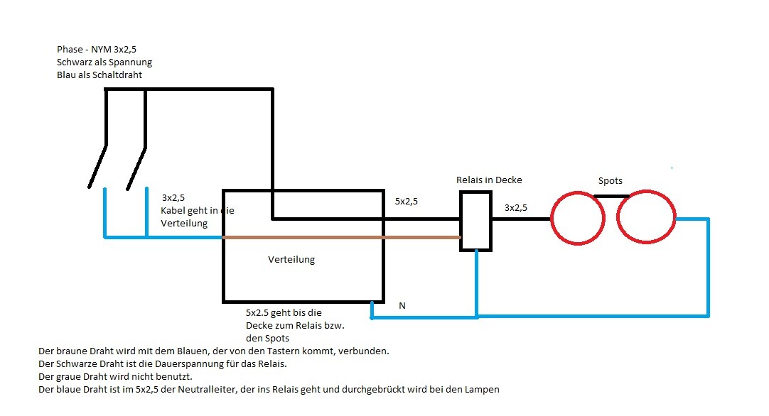
I can sketch this out for you... it might look a bit rough, but it will show you how it could be done.
My training was some years ago, and now I work more in industry than residential construction. So my drawing isn’t great, but it should still work.
On the left, the 3x2.5 cable goes to your switches, and it can’t be replaced. So the blue cable must be switched. In the distribution board, the blue and brown wires are connected via a terminal. So the “signal” is effectively passed through the distribution until it reaches the relay.
The relay is connected with a 5-core cable accordingly, and the relay’s “output” can continue to power the spots with 3x2.5 cable.
Oh, and before I forget—don’t rely too much on the colors. It might be that your switches have brown, blue, and green-yellow wires. In that case, brown is the constant live, and black is switched to the relay.
You say each lighting circuit goes all the way back to the distribution board. So at the switch, there is only one cable coming out of the junction box? Or two, if it’s a double switch.
I don’t want to give incorrect information, and this is a bit of a gray area. In principle, it could work. If it were my house, I’d probably do it that way. The problem is that the blue conductor should only be switched in exceptional cases, and any mix-up must be avoided. Basically, your three-core cable runs to the distribution board, where multiple blue wires are connected together. But the one from your switch is not. So a mix-up is possible.
I can sketch this out for you... it might look a bit rough, but it will show you how it could be done.
My training was some years ago, and now I work more in industry than residential construction. So my drawing isn’t great, but it should still work.
On the left, the 3x2.5 cable goes to your switches, and it can’t be replaced. So the blue cable must be switched. In the distribution board, the blue and brown wires are connected via a terminal. So the “signal” is effectively passed through the distribution until it reaches the relay.
The relay is connected with a 5-core cable accordingly, and the relay’s “output” can continue to power the spots with 3x2.5 cable.
Oh, and before I forget—don’t rely too much on the colors. It might be that your switches have brown, blue, and green-yellow wires. In that case, brown is the constant live, and black is switched to the relay.
danixf schrieb:
I don’t understand why the 3x2.5 cable was installed. 1.5 would have been more than enough and it’s easier to handle during wiring. But that doesn’t really affect the problem.
So you’re saying each lighting circuit runs all the way back to the distribution board. Then there is only one cable coming out of the switch box? Or two, if it’s a double switch. I’m not sure either. Maybe they want to make wiring difficult. Each lighting circuit does indeed run back to the distribution board. And just as you said, there is one cable coming out of the box, and two if it’s a double switch.
Thanks a lot! I’ll discuss this with my electrician. At least he knew that we mostly want switches, so he should implement it that way.
Similar topics