Topic: Electrical wiring—specifically the control of ceiling spotlights. We have the following situation:
We have an open-plan living/dining area with a kitchen of about 80 m² (860 ft²). This means we have several zones of ceiling spotlights. The living area, dining area, and kitchen are the main zones. For example, in the living area, we have divided the ceiling spotlights into two separate zones (this is due to the ceiling construction resulting from converting a barn into living space).
I will explain this using the example of the two zones of ceiling spotlights in the living area. These two zones should be controllable separately; for this, we have planned double rocker switches. By the way, all the ceiling spotlights should be dimmable. This one double rocker switch for the living area is located in three places within the large room. Now, we don’t want a dimmable double rocker switch but rather a dimmable double push-button switch. For this, ELTAKO units could have been installed in the distribution board (as far as I understand, being a layperson). We did not do this. Now there are surface-mounted ELTAKO units. The problem is that one would fit into a standard surface-mounted box, but according to the electrician, two would not. Can someone help us solve this problem? I hope I have explained this clearly enough. If not, please feel free to ask questions.
Hello Mycraft,
I need to come back to this topic again. You’ve already helped me a lot, but I would like to briefly summarize everything and ask if I have understood it correctly (since I don’t have 100 posts yet, I can’t start a private conversation):
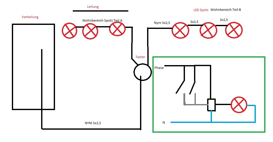
So, we have installed NYM 3 x 2.5 cables and want to dim ceiling spotlights using a double rocker switch. The ELTAKOs don’t fit into the flush-mounted box. There is enough space on the OSB/drywall ceiling. Now, using your "wiring diagram"/"drawing," we can simply install the ELTAKOs in front of the ceiling spotlights, and then everything should work?
Another electrician I spoke with by phone, to whom I explained the situation, mentioned that we don’t have a constant power supply— which would be needed (however, he didn’t see your drawing).
Have I understood this correctly? Or could you please explain it once more in very simple terms? It would really help us!
Of course, other responses are also very welcome.
I need to come back to this topic again. You’ve already helped me a lot, but I would like to briefly summarize everything and ask if I have understood it correctly (since I don’t have 100 posts yet, I can’t start a private conversation):
So, we have installed NYM 3 x 2.5 cables and want to dim ceiling spotlights using a double rocker switch. The ELTAKOs don’t fit into the flush-mounted box. There is enough space on the OSB/drywall ceiling. Now, using your "wiring diagram"/"drawing," we can simply install the ELTAKOs in front of the ceiling spotlights, and then everything should work?
Another electrician I spoke with by phone, to whom I explained the situation, mentioned that we don’t have a constant power supply— which would be needed (however, he didn’t see your drawing).
Have I understood this correctly? Or could you please explain it once more in very simple terms? It would really help us!
Of course, other responses are also very welcome.

Then it would have to be 4-core cables, right? Unfortunately, they are only 3-core. Can I run or have an additional cable installed separately for the constant power supply to the Eltakos? As mentioned, space is not an issue, and we have specifically installed empty conduits up to the attic. So that would not be a problem; everything is easily accessible.
With an additional cable, it would be easy to disconnect. I don’t fully understand your setup yet. Do you have an empty conduit all the way to the spotlights? Then you just need to pull a 3x1.5mm² (3x1.5mm² (about 5x16 AWG)) cable from there to the distribution board. Or does the conduit only go up to the switch? Basically, that would still work.
You could then use the switch to take the brown/black wire as the live supply and the blue wire as the "output," connecting it to the relay located in the distribution board. So you would have constant live voltage on the phase conductor and switch the blue wire. However, this method is widely debated and at least not recommended. Feel free to look up "neutral/blue wire as a switched conductor." This only works if all the cables run back to the distribution board.
With a 5x1.5mm² (5x1.5mm² (about 5x16 AWG)) cable (4-core cables are usually not used, you go directly to 5-core, which is also cheaper than 4-core), it would look like this. I attached a picture. The part in the green box is just to show how it looks with a cable that has more than 3 cores. You use one as the live conductor going to the switches and bridged in the flush-mounted junction box. This way, the relay in your ceiling has constant live voltage. The lights are connected accordingly there.
You use another conductor as the switched wire. When you press the switches, it sends voltage to an input on the relay, which then dims the spotlights.
The illustration on the left is just to show how I currently understand it.
Let me try to describe it again. First of all, thank you very much for the help. So:
Basically, the electrical rough-in is completely finished (plaster and screed are also done). Outlets are installed. Now the electrician wanted to mount switches and push buttons (the recessed ceiling lights are not installed yet). For all of these, 3 x 2.5 mm² cables were installed. Of course, each lighting circuit runs all the way to the distribution panel. We have all rooms on the ground floor. The attic will not be converted. Below, we have exposed wooden beams, on top of which there is drywall and OSB boards. Above that, wooden beams run across. Between the wooden beams, 20 cm (8 inches) of insulation will be installed. The recessed ceiling lights will basically be installed within the insulation. Since the insulation is not installed yet and everything is open, we have space. As a precaution, we ran power and two empty conduit pipes from the lighting distribution on the ground floor up to the attic. So, in principle, we have power up there. I hope this is a bit clearer now, and I hope it is still possible.
Basically, the electrical rough-in is completely finished (plaster and screed are also done). Outlets are installed. Now the electrician wanted to mount switches and push buttons (the recessed ceiling lights are not installed yet). For all of these, 3 x 2.5 mm² cables were installed. Of course, each lighting circuit runs all the way to the distribution panel. We have all rooms on the ground floor. The attic will not be converted. Below, we have exposed wooden beams, on top of which there is drywall and OSB boards. Above that, wooden beams run across. Between the wooden beams, 20 cm (8 inches) of insulation will be installed. The recessed ceiling lights will basically be installed within the insulation. Since the insulation is not installed yet and everything is open, we have space. As a precaution, we ran power and two empty conduit pipes from the lighting distribution on the ground floor up to the attic. So, in principle, we have power up there. I hope this is a bit clearer now, and I hope it is still possible.
Similar topics