ᐅ Hydraulic short circuit? Radiator return line on the upper floor warmer than the supply line
Created on: 18 Nov 2023 18:45
T
Theo984Good evening everyone,
In January of this year, we had an Arotherm Plus installed and, during this process, the fixed-value control unit of the underfloor heating was replaced (the actuator was defective, and no spare parts were available). The ground floor has underfloor heating, and the upper floor has radiators (which were replaced with Type 33 radiators during the renovation). The fixed-value control unit installed by the heating contractor did not work at all, so it was replaced with a Purmo Tempco Fix 3 Eco fixed-value control unit.
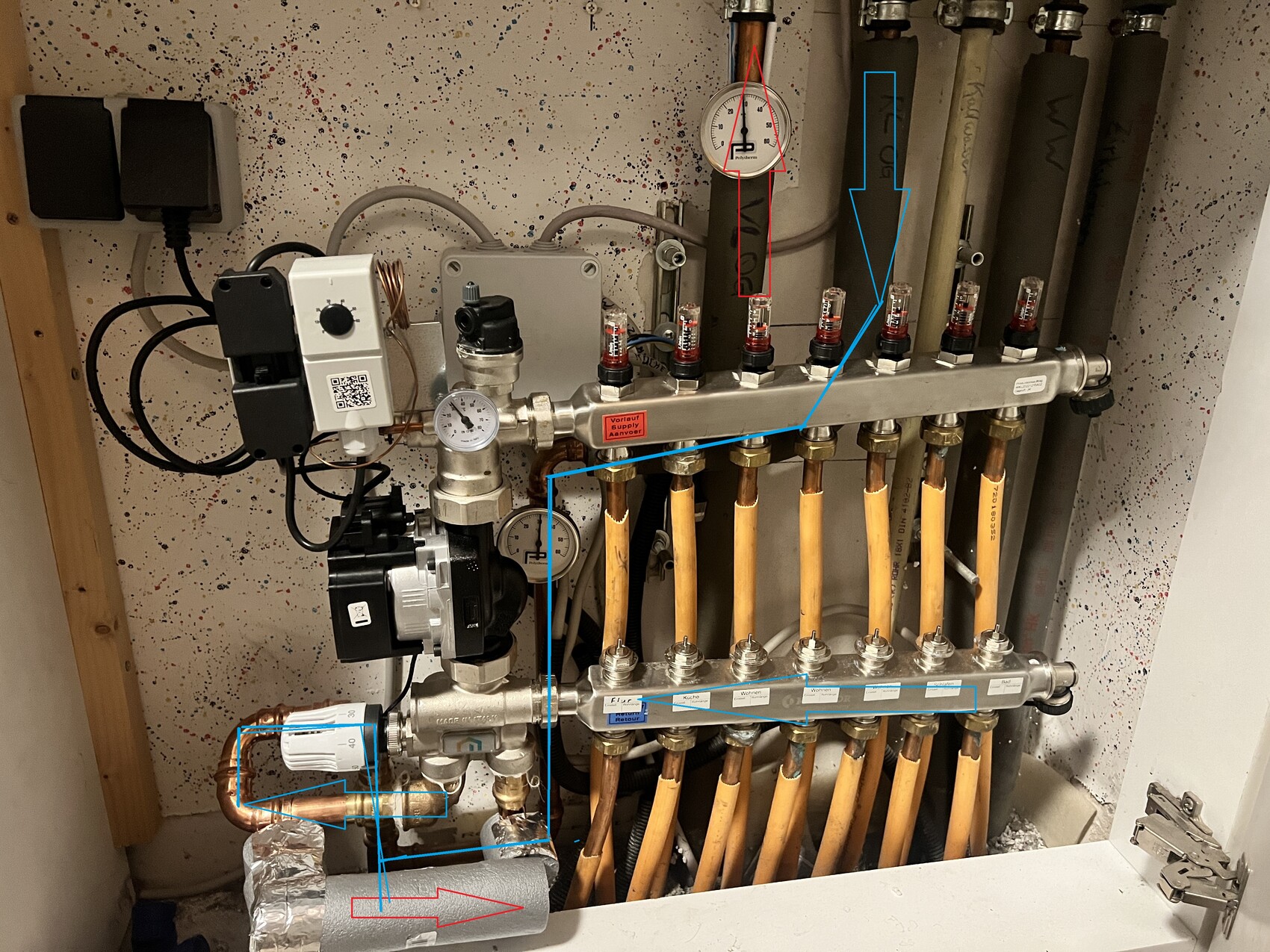
Unfortunately, the return flow temperature of the upper floor circuit is still higher than the supply flow. The upper floor return flow merges with the underfloor heating return flow (I hope this can be seen in the photo), and this seems to be where the problem lies. The pressure from the underfloor heating appears to be too high, pushing into the return of the upper floor circuit.
For me, there are two possible solutions:
1. Separate the two heating circuits, at least the return flows, up to just before the heat pump. The supply flow temperature would remain the same.
2. Integrate the upper floor return flow between the underfloor heating return and the fixed-value control unit, so that it uses both return flows for mixing and then sends the combined flow back to the heat pump through one pipe. The issue here is the available space and the connection.
What do you think about these options? Are there maybe other ideas? And is this a defect that the heating contractor needs to fix?
Thanks in advance and have a nice evening!
In January of this year, we had an Arotherm Plus installed and, during this process, the fixed-value control unit of the underfloor heating was replaced (the actuator was defective, and no spare parts were available). The ground floor has underfloor heating, and the upper floor has radiators (which were replaced with Type 33 radiators during the renovation). The fixed-value control unit installed by the heating contractor did not work at all, so it was replaced with a Purmo Tempco Fix 3 Eco fixed-value control unit.
Unfortunately, the return flow temperature of the upper floor circuit is still higher than the supply flow. The upper floor return flow merges with the underfloor heating return flow (I hope this can be seen in the photo), and this seems to be where the problem lies. The pressure from the underfloor heating appears to be too high, pushing into the return of the upper floor circuit.
For me, there are two possible solutions:
1. Separate the two heating circuits, at least the return flows, up to just before the heat pump. The supply flow temperature would remain the same.
2. Integrate the upper floor return flow between the underfloor heating return and the fixed-value control unit, so that it uses both return flows for mixing and then sends the combined flow back to the heat pump through one pipe. The issue here is the available space and the connection.
What do you think about these options? Are there maybe other ideas? And is this a defect that the heating contractor needs to fix?
Thanks in advance and have a nice evening!
R
RotorMotor18 Nov 2023 19:12That sounds very odd.
How did you measure that?
What is the actual problem?
Is it not getting warm? Is the energy consumption too high?
Do you have a diagram of the hydraulic system or can you create one?
How did you measure that?
What is the actual problem?
Is it not getting warm? Is the energy consumption too high?
Do you have a diagram of the hydraulic system or can you create one?
Good evening,
I measured the temperatures with two thermostats directly on the pipes (which can also be seen in the photo: supply line just under 29°C (84°F), return line about 30.5°C (87°F)).
The main issue is the consumption (COP) or the frequent cycling at temperatures where it should just run continuously (COP 2.9 at 2°C (36°F) outdoor temperature, according to Vaillant it should be above 4).
It is heating up properly now, which I have managed so far. I could probably lower the supply temperature further once the problem is resolved. I can gladly create and upload a hydraulic diagram tomorrow.
Good morning,
Attached are a simple drawing and a photo showing flow directions. The problem area is marked with a yellow circle, where it seems that the pressure from the underfloor heating return line is so high that it is pushing into the upper floor return line.
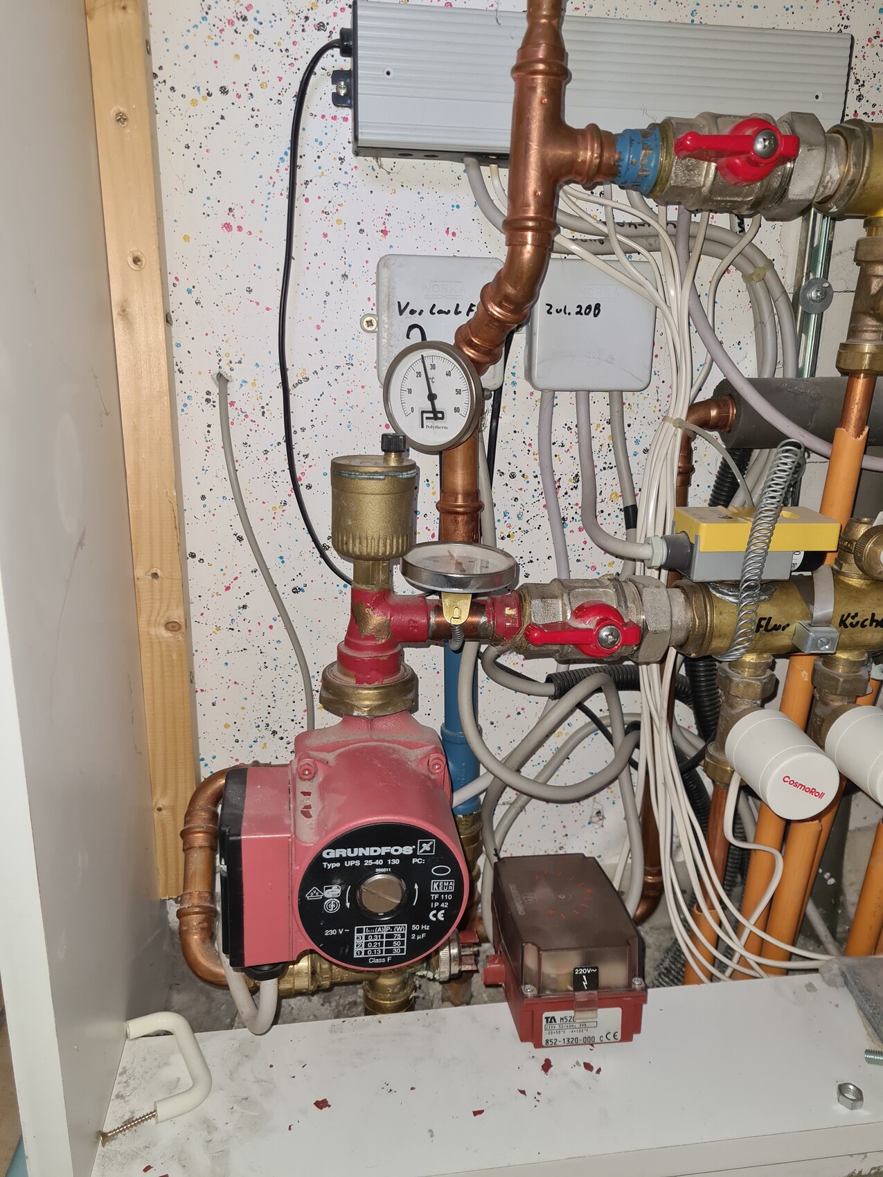
The house’s hydraulic system does not appear to be working well under the current conditions, as the system was set up differently before the renovation. I have included a photo of the previous setup, in which the underfloor heating circulation pump drew suction from the underfloor heating return line, so pressure in the system was generated only in the supply line, and not, as is the case now, also in the return line.
I hope this is clear so far?! ,-)
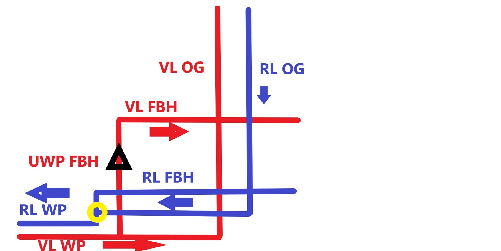
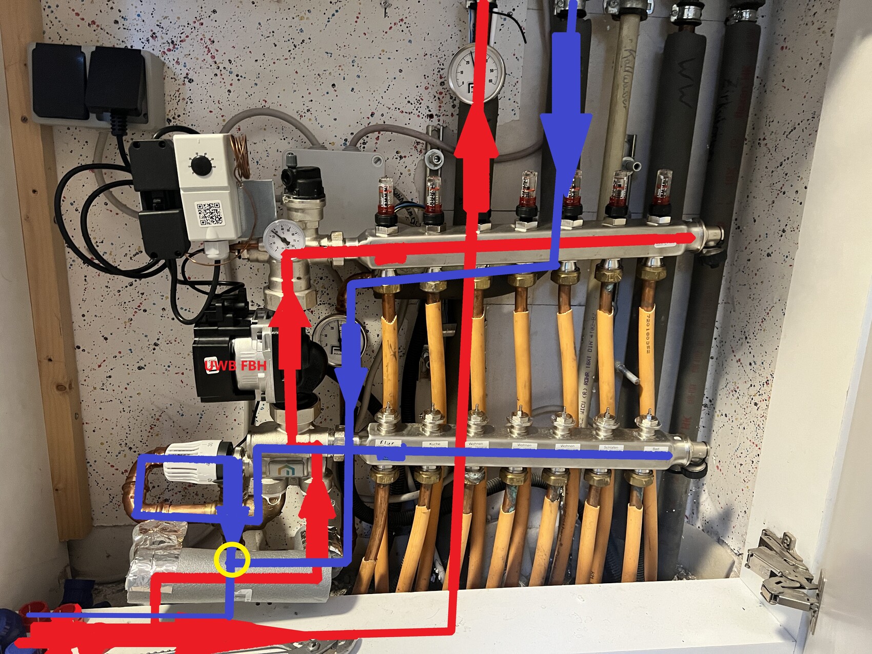
Attached are a simple drawing and a photo showing flow directions. The problem area is marked with a yellow circle, where it seems that the pressure from the underfloor heating return line is so high that it is pushing into the upper floor return line.
The house’s hydraulic system does not appear to be working well under the current conditions, as the system was set up differently before the renovation. I have included a photo of the previous setup, in which the underfloor heating circulation pump drew suction from the underfloor heating return line, so pressure in the system was generated only in the supply line, and not, as is the case now, also in the return line.
I hope this is clear so far?! ,-)
R
RotorMotor19 Nov 2023 11:27We need the complete hydraulic system, not just the small section. Normally, the air-to-water heat pump would directly push into the heating circuits with the integrated water pump.
Here, I see an extra pump in an "interesting" location. Why is that? Are there buffers, etc.? Is it possible that the thermometers are simply inaccurate? What does the thermostat do in the manifold?
Here, I see an extra pump in an "interesting" location. Why is that? Are there buffers, etc.? Is it possible that the thermometers are simply inaccurate? What does the thermostat do in the manifold?
Good evening,
tomorrow I will try to draw a complete hydraulic plan, although I have never done this before.
Brief overview of the setup: downstairs there are 5 rooms with underfloor heating, upstairs 4 rooms with radiators. The distribution can be seen in the photo, with the air-to-water heat pump located in front of it. :-)
It is correct that the air-to-water heat pump (Arotherm Plus 75/6 with Unitower Plus 190) includes a circulation pump. The additional pump was installed during the heating system renovation due to a defect in the old system (the red Grundfos circulation pump / mixing valve on the plastic housing was broken). As a layperson, I actually assumed that the second circulation pump for the underfloor heating was absolutely necessary. Thinking it through now, that seems rather pointless, since mixing is not required or intended because I run the same supply temperature for both the underfloor heating and the radiators (which were replaced with Type 33 for a lower supply temperature).
Inside the air-to-water heat pump there is a 35-liter (9.2 gallons) buffer tank on the return side; the heating contractor insisted on this. The bypass valve is closed as much as possible, the differential pressure controllers were removed, and a hydraulic balancing was carried out based on flow rates.
The thermostats were actually taken over from the old system for my own tracking, but the readings were plausible, since the return to the radiators upstairs was warmer than the supply. Of course, it is still possible that the values are not accurate; I am planning to get an IR thermometer to verify this more precisely.
Similar topics