W
Wacholder6 Dec 2020 12:38Hello forum community,
I plan to refurbish an existing old garage without electrical installation.
Three supply lines have already been installed by a professional company.
I only want to do the wiring, install the lights, sockets, etc.; the final connection will be done by a certified professional (before anyone criticizes me or tells me to leave it alone).
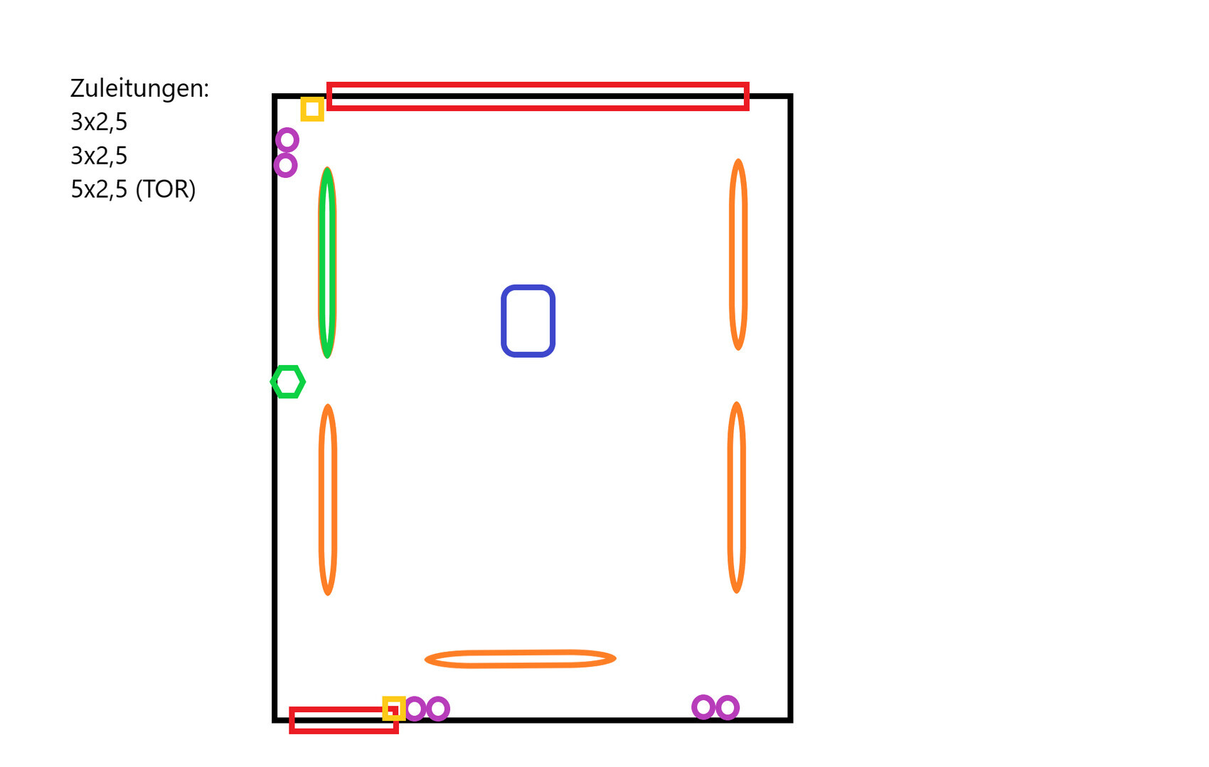
The following is planned (see sketch):
- Garage door and rear exit door (red rectangles)
- The garage has an electric door opener (blue rectangle)
- The garage will have 5 LED tube lights installed on the ceiling (4x orange, 1x green oval)
- Light switches are planned next to the garage door and rear door (yellow rectangles)
- All switches should control all 5 LED tubes
- One of the 5 tubes should also be controlled by a motion sensor (on/delayed off) (green oval and green hexagon)
- Power outlets are desired on two walls (lighting circuit only) (purple circles)
I would really appreciate if someone could help me with a plan showing where to route the cables and where junction boxes etc. would make sense.
I would not consider myself unskilled, but I want to avoid costly mistakes as much as possible.
The installation will be surface-mounted, so I am looking for the most practical and efficient solution.
Sorry for the quality of the sketch, but photos do not help at the moment (-;
I plan to refurbish an existing old garage without electrical installation.
Three supply lines have already been installed by a professional company.
I only want to do the wiring, install the lights, sockets, etc.; the final connection will be done by a certified professional (before anyone criticizes me or tells me to leave it alone).
The following is planned (see sketch):
- Garage door and rear exit door (red rectangles)
- The garage has an electric door opener (blue rectangle)
- The garage will have 5 LED tube lights installed on the ceiling (4x orange, 1x green oval)
- Light switches are planned next to the garage door and rear door (yellow rectangles)
- All switches should control all 5 LED tubes
- One of the 5 tubes should also be controlled by a motion sensor (on/delayed off) (green oval and green hexagon)
- Power outlets are desired on two walls (lighting circuit only) (purple circles)
I would really appreciate if someone could help me with a plan showing where to route the cables and where junction boxes etc. would make sense.
I would not consider myself unskilled, but I want to avoid costly mistakes as much as possible.
The installation will be surface-mounted, so I am looking for the most practical and efficient solution.
Sorry for the quality of the sketch, but photos do not help at the moment (-;
W
Wacholder7 Dec 2020 20:17Thanks for the response. In the meantime, I was able to clarify a few things. The 5-core cable is for a two-way switch controlling an outdoor lighting system, which is connected via a 3x1.5 mm² (3x1.5 mm² / 3x0.015 m²) cable. For the internal lighting and power outlets, a 3x1.5 mm² (3x1.5 mm² / 3x0.015 m²) cable is planned. I now need a wiring plan for this 3-core cable to connect the lights and outlets.

It is important to know the cable length from the circuit breaker to the farthest outlet because of the size of the circuit protection.
(loop impedance)
I would recommend a feeder cable of at least 5x 6mm² (5x 0.01 inch²) and a sub-distribution board with an RCD. If an electric car is added later, this setup can be upgraded accordingly.
With 5x 6mm² (5x 0.01 inch²), the cable length must also be taken into account.
(loop impedance)
I would recommend a feeder cable of at least 5x 6mm² (5x 0.01 inch²) and a sub-distribution board with an RCD. If an electric car is added later, this setup can be upgraded accordingly.
With 5x 6mm² (5x 0.01 inch²), the cable length must also be taken into account.
Similar topics