ᐅ Flow rate setting for underfloor heating at the manifold in liters per minute (L/min)
Created on: 27 Dec 2022 12:53
V
vaderle
Hello everyone,
I have set a desired temperature of 21.5°C (70.7°F) on my heating system (air-to-water heat pump) at the bottom. The room thermostats are all fully open (set to 33°C (91.4°F)).
So far so good. Almost all rooms reach 21.5°C (70.7°F). Only in the bedroom (upstairs) does it reach a maximum of 20.7°C (69.3°F). Now I wanted to increase the flow rate slightly at the distribution manifold. According to my online research, you only need to turn the red cap on the flow indicator to increase or decrease the flow. This should allow more warm water to reach the room and raise the temperature.
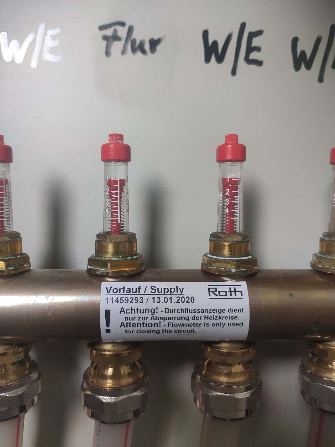
However, below the flow indicator, I found a sticker from the heating installer. The sticker says “Warning! The flow indicator serves only to shut off the heating circuits.” (see the photo)
Does this mean that fine adjustments cannot be made there at all? Where else can the flow rate in liters per minute be adjusted?
Does this mean that fine adjustments cannot be made there at all? Where else can the flow rate in liters per minute be adjusted?
I have set a desired temperature of 21.5°C (70.7°F) on my heating system (air-to-water heat pump) at the bottom. The room thermostats are all fully open (set to 33°C (91.4°F)).
So far so good. Almost all rooms reach 21.5°C (70.7°F). Only in the bedroom (upstairs) does it reach a maximum of 20.7°C (69.3°F). Now I wanted to increase the flow rate slightly at the distribution manifold. According to my online research, you only need to turn the red cap on the flow indicator to increase or decrease the flow. This should allow more warm water to reach the room and raise the temperature.
However, below the flow indicator, I found a sticker from the heating installer. The sticker says “Warning! The flow indicator serves only to shut off the heating circuits.” (see the photo)
Does this mean that fine adjustments cannot be made there at all? Where else can the flow rate in liters per minute be adjusted?
Does this mean that fine adjustments cannot be made there at all? Where else can the flow rate in liters per minute be adjusted?
halmi schrieb:
They break... we also have a Roth manifold.
The key is for the valve below the actuators (the dark gray parts where the red cap is visible at the flow).Thanks for the tip. Do they break immediately if you turn them even just one full turn? Unfortunately, I already tried turning one of those red caps once as a test 😱 Is there any way to check (for example, if the flow rate drops to 0 liters per minute) to see if something got damaged?
Hello everyone,
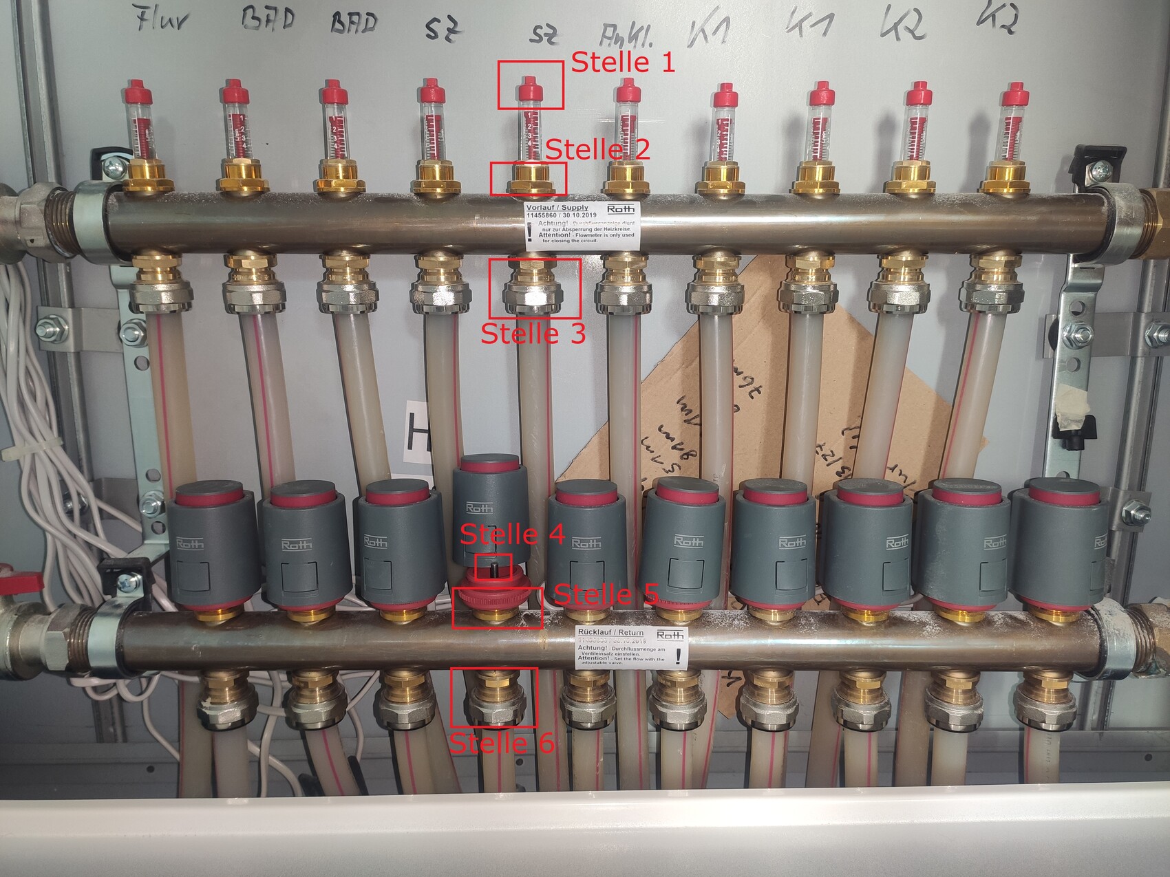
I have some follow-up questions regarding the use of the Roth system and have created a new image with labeled positions.
According to the Roth sticker on top, the indicator on the supply line is only for shutting off the heating circuit. Exactly where do you shut off the heating circuit? At position 1, 2, or 3? Can you tell from the indicator whether a heating circuit has been shut off (for example, does the float in the glass rise to zero or drop all the way down)? I accidentally turned something at position 1 because I thought it was where you adjust the flow rate. Now I’m unsure if I have shut off the heating circuit by doing that (if position 1 is indeed the shut-off point).
Where exactly do you adjust the flow rate at the bottom on the return line? At position 4, 5, or 6? Is the change immediately visible on the indicator above, and does turning clockwise decrease the flow and counterclockwise increase it?
R
RotorMotor5 Jan 2023 11:55If you have adjusted position 1, it would make sense to turn position 1 back, wouldn’t it? ;-)
You can read the flow rate on the sight glass below position 1; at the top it shows 0, at the bottom 5.
You can limit the flow rate at position 4 using a standard heating square key. To limit, turn clockwise. It may take a few turns before you notice any change. After that, small adjustments will affect the flow rate, which you can again read from the top.
Is the following logic also true for position 1?
Clockwise = close heating circuit
Counterclockwise = open heating circuit
So, I would need to turn it slightly counterclockwise. Is there a stop, or will I eventually unscrew the glass part?
By the way, this concerns the two bedroom circuits. Or can you tell from the picture whether the two heating circuits are normally open?