ᐅ Construction Details: Gap Between Ring Beam and Timber Flat Roof
Created on: 23 Nov 2025 20:21
T
tenspoplin5s
Hi,
I was advised that I might get better help here in this forum.
We are having our roof constructed by a carpentry company. It is a warm roof with 25mm OSB4 as the sheathing, followed by a vapor barrier (approved bitumen membrane with sd > 100m), then 140mm aluminum-coated PIR insulation, 1.5mm EPDM membrane, and a green roof on top.
The masonry is 425mm aerated concrete, with a ring beam around it. On the outside is 100mm XPS insulation, and on the inside 325mm reinforced concrete.
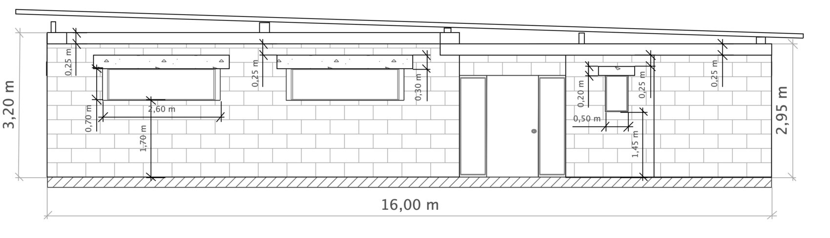
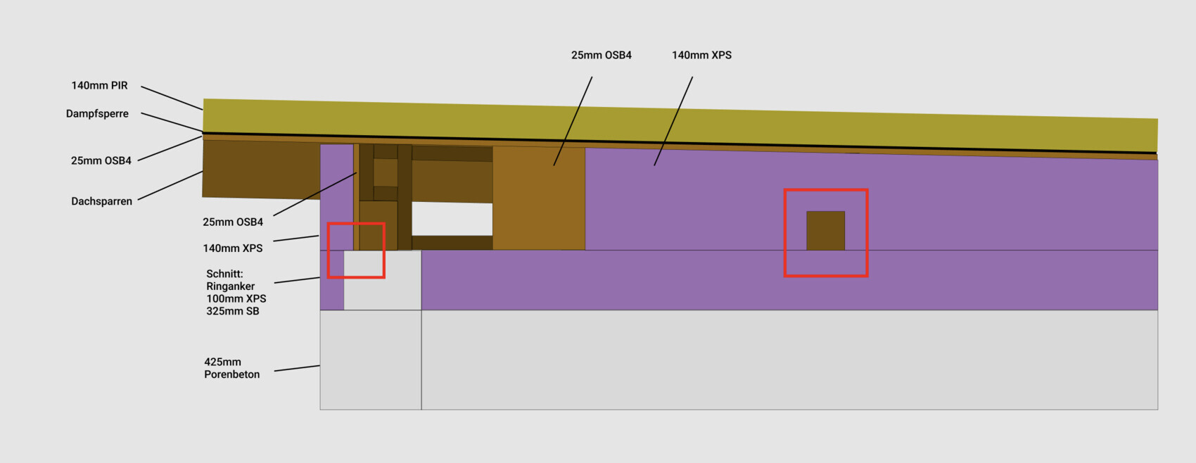
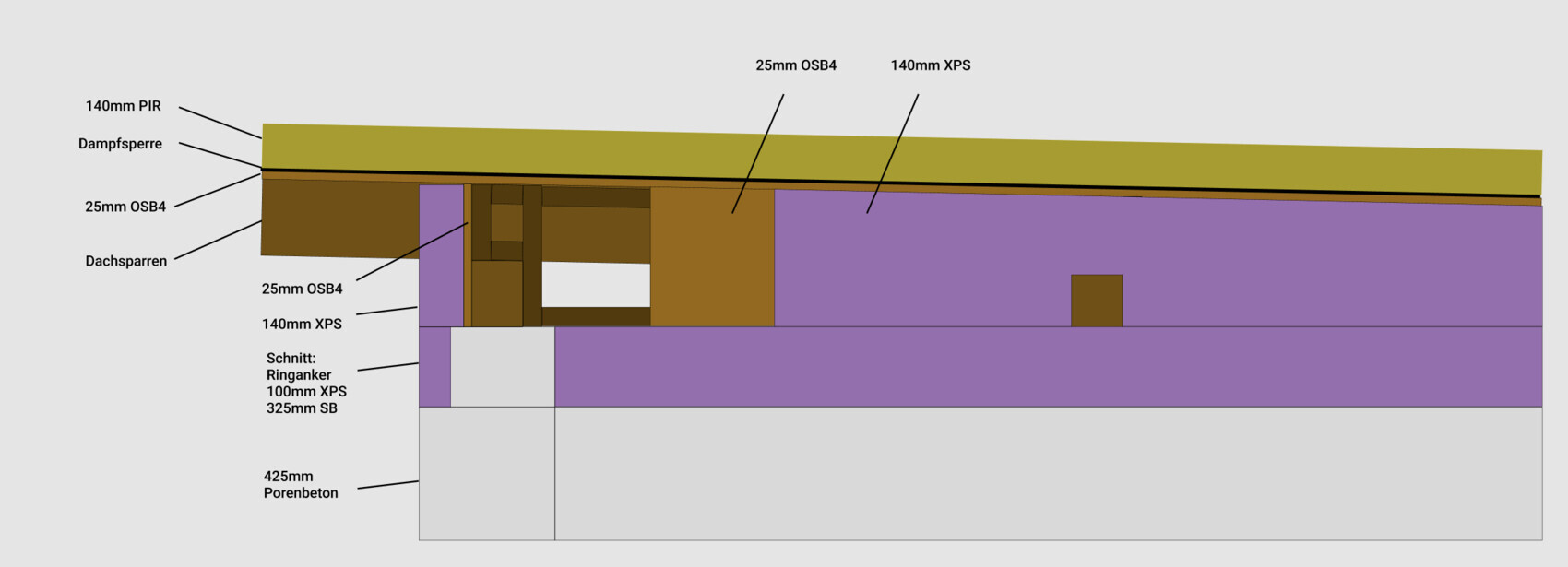
The ring beam runs continuously and horizontally, without any slope. The roof is pitched with a 2% slope over 16m along the rafters. Due to the building’s depth of almost 16m, trapezoidal cavities form between the ring beam and the roof sheathing, which need to be filled somehow. From the outside, you can basically look directly into these spaces. Here is a side view showing the basic situation:
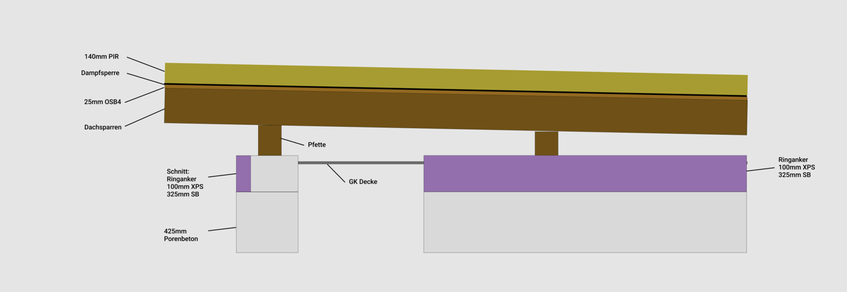
And here is a detailed view for the construction method:
The carpentry company wants to fill these spaces with timber frame construction and install a 60mm wood fiberboard as a plaster base on top. Then, from the outside, a ventilated wooden facade and plaster will be applied in some areas.
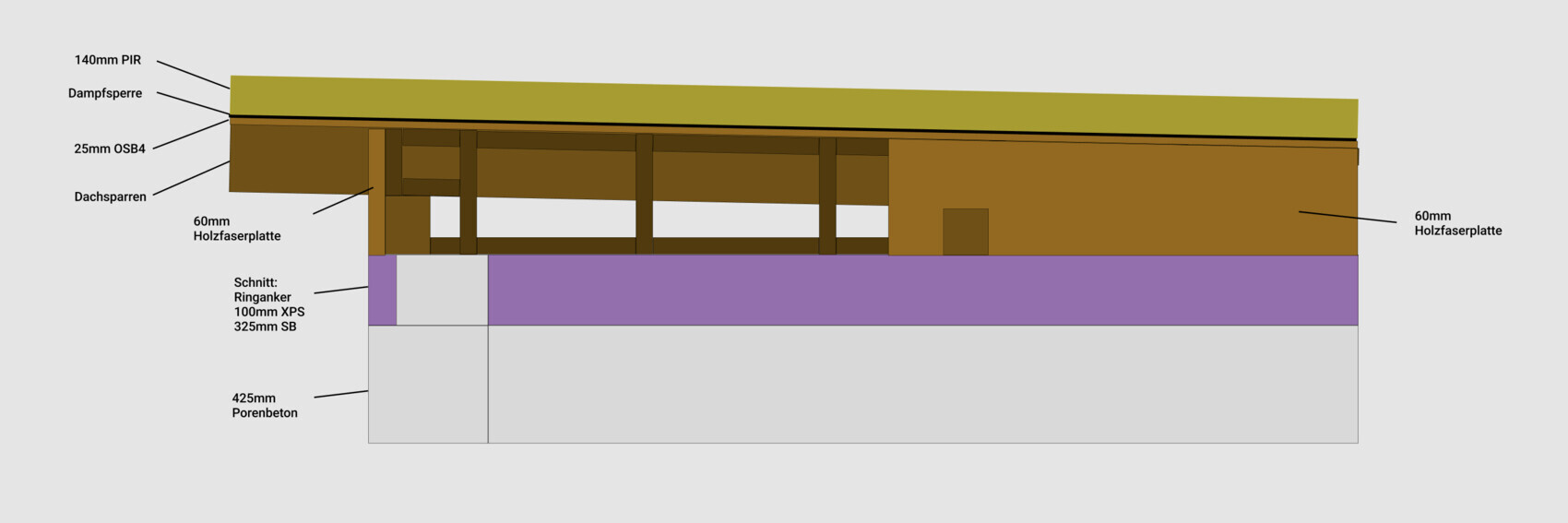
Front view:
Now there have been discussions that all these small “stud frame” sections would need to be insulated, since the 60mm wood fiberboard on its own does not provide sufficient insulation.
Because there are dozens of these small frame sections, this would be a tedious job, and filling them with mineral wool, blown-in insulation, or spraying with polyurethane foam would all be cumbersome and potentially unreliable. This could result in uneven insulation and gaps.
So I came up with the following idea: instead of the 60mm wood fiberboard, use a 25mm OSB4 sheathing with 140mm XPS insulation applied on top. This would place the entire wooden structure on the warm side, similar to the roof assembly.
If the insulation is installed properly (no air leakage from outside to inside, joints and gaps foamed), I assume there will be no condensation in the wood areas, since the dew point even under extreme conditions (inside 20°C (68°F), outside -10°C (14°F)) will remain within the insulation layer. In the end, it is the same situation as on the roof, except that the vapor barrier is missing here and implicitly replaced by the XPS.
I see critical points marked in red.
Here, the insulation on the ring beam is only 100mm thick, so the reinforced concrete will be colder and might be within the dew point range in extreme scenarios.
At locations where beam ends (for example due to roof overhang) protrude to the outside, the insulation is interrupted. The beams will be colder inside than the insulation itself. Is there a risk of condensation forming?
Could you please give me your assessment on whether my approach could work and where you see potential risks?
An alternative would be to increase the wood fiberboard thickness to about 140mm instead of 60mm. In this case, these cavities would be slightly less insulated but remain vapor permeable, allowing any moisture to dry outwards if it occurs.
I was advised that I might get better help here in this forum.
We are having our roof constructed by a carpentry company. It is a warm roof with 25mm OSB4 as the sheathing, followed by a vapor barrier (approved bitumen membrane with sd > 100m), then 140mm aluminum-coated PIR insulation, 1.5mm EPDM membrane, and a green roof on top.
The masonry is 425mm aerated concrete, with a ring beam around it. On the outside is 100mm XPS insulation, and on the inside 325mm reinforced concrete.
The ring beam runs continuously and horizontally, without any slope. The roof is pitched with a 2% slope over 16m along the rafters. Due to the building’s depth of almost 16m, trapezoidal cavities form between the ring beam and the roof sheathing, which need to be filled somehow. From the outside, you can basically look directly into these spaces. Here is a side view showing the basic situation:
And here is a detailed view for the construction method:
The carpentry company wants to fill these spaces with timber frame construction and install a 60mm wood fiberboard as a plaster base on top. Then, from the outside, a ventilated wooden facade and plaster will be applied in some areas.
Front view:
Now there have been discussions that all these small “stud frame” sections would need to be insulated, since the 60mm wood fiberboard on its own does not provide sufficient insulation.
Because there are dozens of these small frame sections, this would be a tedious job, and filling them with mineral wool, blown-in insulation, or spraying with polyurethane foam would all be cumbersome and potentially unreliable. This could result in uneven insulation and gaps.
So I came up with the following idea: instead of the 60mm wood fiberboard, use a 25mm OSB4 sheathing with 140mm XPS insulation applied on top. This would place the entire wooden structure on the warm side, similar to the roof assembly.
If the insulation is installed properly (no air leakage from outside to inside, joints and gaps foamed), I assume there will be no condensation in the wood areas, since the dew point even under extreme conditions (inside 20°C (68°F), outside -10°C (14°F)) will remain within the insulation layer. In the end, it is the same situation as on the roof, except that the vapor barrier is missing here and implicitly replaced by the XPS.
I see critical points marked in red.
Here, the insulation on the ring beam is only 100mm thick, so the reinforced concrete will be colder and might be within the dew point range in extreme scenarios.
At locations where beam ends (for example due to roof overhang) protrude to the outside, the insulation is interrupted. The beams will be colder inside than the insulation itself. Is there a risk of condensation forming?
Could you please give me your assessment on whether my approach could work and where you see potential risks?
An alternative would be to increase the wood fiberboard thickness to about 140mm instead of 60mm. In this case, these cavities would be slightly less insulated but remain vapor permeable, allowing any moisture to dry outwards if it occurs.
If you really want to ensure consistency in the details, choose a clean approach: apply the XPS layer continuously across the entire structure, including over the tapered insulation zone and the top of the studs. Then install a continuous OSB sheathing in front of it to keep everything airtight and structurally rigid. This completely eliminates local cold spots. The infill panels in this area are not necessarily required for structural purposes. So why not simplify radically by removing the studs there instead of trying to wrap them in a complicated way? This thickening in the middle acts like an unnecessary foreign element within the insulation layer.
T
tenspoplin5s23 Nov 2025 22:07I might be a bit confused here :-)
“Extend the XPS layer continuously across the entire structure.”
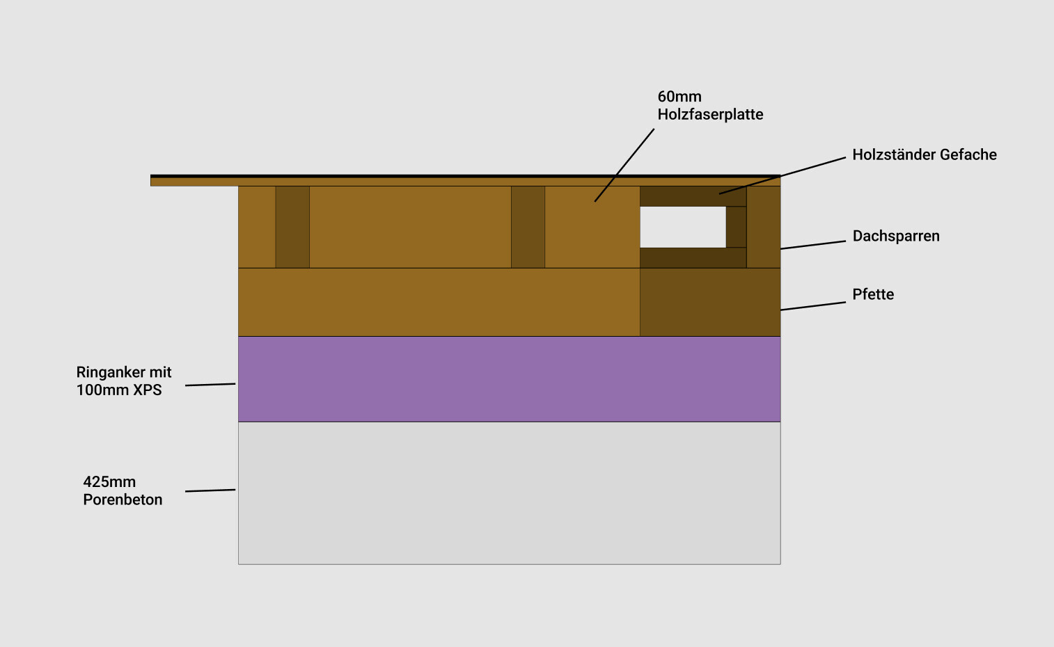
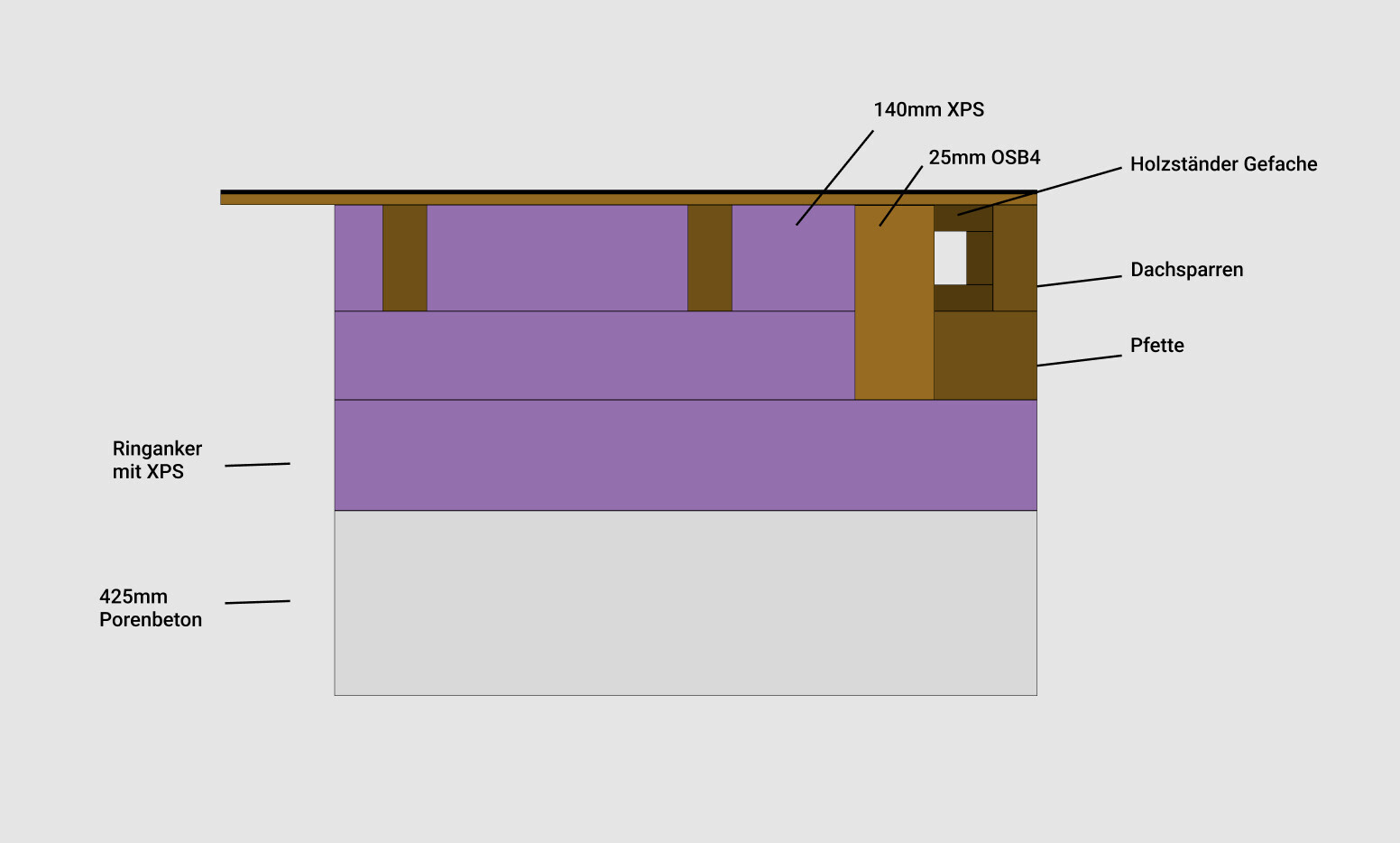
That’s actually exactly what I’m trying to achieve here (you can see multiple layers stacked one after another so it’s clear what’s behind each layer—I hope the illustration is understandable):
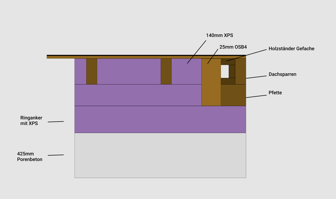
Here again, multiple layers in sequence. On the far left is the sectional view of the graphic shown above:
I have the XPS flush with the exterior wall (since there’s already XPS at the ring beam), and the OSB4 board behind it in the wedge zone or in the gaps between the rafter ends that are visible.
“... and the stud heads”—this is physically not possible. The heads protrude on all sides because we have roof eaves all around. I can only enclose the rafter ends with insulation (and OSB), but they will always stick out.
The edges of the XPS insulation would be sealed with PU foam.
How should I handle the fact that the ring beam only has 10cm (4 inches) of XPS and that, in a worst-case scenario, the reinforced concrete behind it might reach the dew point at one spot? Is this mostly theoretical, or is it a real risk?
---
Someone else told me to leave the 60mm (2.4 inches) wood fiber insulation on the outside and stuff the cavities inside with mineral wool, then install a vapor barrier in front—but as far as I know, that’s a building physics no-go. The wooden structure in my warm roof assembly has to always be on the warm side, including in the wedge zone between the wall and the roof.
“Extend the XPS layer continuously across the entire structure.”
That’s actually exactly what I’m trying to achieve here (you can see multiple layers stacked one after another so it’s clear what’s behind each layer—I hope the illustration is understandable):
Here again, multiple layers in sequence. On the far left is the sectional view of the graphic shown above:
I have the XPS flush with the exterior wall (since there’s already XPS at the ring beam), and the OSB4 board behind it in the wedge zone or in the gaps between the rafter ends that are visible.
“... and the stud heads”—this is physically not possible. The heads protrude on all sides because we have roof eaves all around. I can only enclose the rafter ends with insulation (and OSB), but they will always stick out.
The edges of the XPS insulation would be sealed with PU foam.
How should I handle the fact that the ring beam only has 10cm (4 inches) of XPS and that, in a worst-case scenario, the reinforced concrete behind it might reach the dew point at one spot? Is this mostly theoretical, or is it a real risk?
---
Someone else told me to leave the 60mm (2.4 inches) wood fiber insulation on the outside and stuff the cavities inside with mineral wool, then install a vapor barrier in front—but as far as I know, that’s a building physics no-go. The wooden structure in my warm roof assembly has to always be on the warm side, including in the wedge zone between the wall and the roof.
Well, you planned the XPS layer carefully, but exactly at the point where the wall, ring beam, and the small studs meet, a zone appears that no longer functions as a continuous surface. The issue is less about the insulation thickness and more about the geometry. Such wedges behave thermally differently than a straight cut. I would extend the XPS layer forward until you actually have a flat, continuous line. The tops of the studs will remain visible due to construction requirements, of course. However, you can fully wrap them and seal the joints so that they no longer act as thermal disruption points. The 10cm (4 inches) of XPS at the ring beam is not critical as long as you have no convective leaks. Moisture there is more likely caused by drafts than by temperature alone.
T
tenspoplin5s23 Nov 2025 22:52The problem is less about the thickness of the insulation and more about the geometry. Such wedges behave differently in terms of thermal performance compared to a straight cut. I would extend the XPS layer forward until you actually have a flat, continuous line.
I have to apologize again; I’m having trouble following you here.
Could you possibly provide a simple sketch? A quick hand-drawn photo would be enough 😀
Just so I understand what you mean by the “continuous line” and what exactly isn’t “continuous” in my case right now.
Thank you!!
I have to apologize again; I’m having trouble following you here.
Could you possibly provide a simple sketch? A quick hand-drawn photo would be enough 😀
Just so I understand what you mean by the “continuous line” and what exactly isn’t “continuous” in my case right now.
Thank you!!
By "continuous line," I simply mean: just create a single, flat XPS surface without offsets, steps, or side recesses. In your case, the insulation noticeably steps back in the wedge area because the OSB is installed behind it. However, from an energy perspective, only the outermost layer matters, not the position of your beams. If you align the XPS flush with the outermost contour, you create a flat plane, regardless of the construction behind it.
Similar topics