ᐅ Mechanical ventilation with heat recovery – is the design suitable?
Created on: 12 Jun 2014 09:09
H
HampekHello everyone,
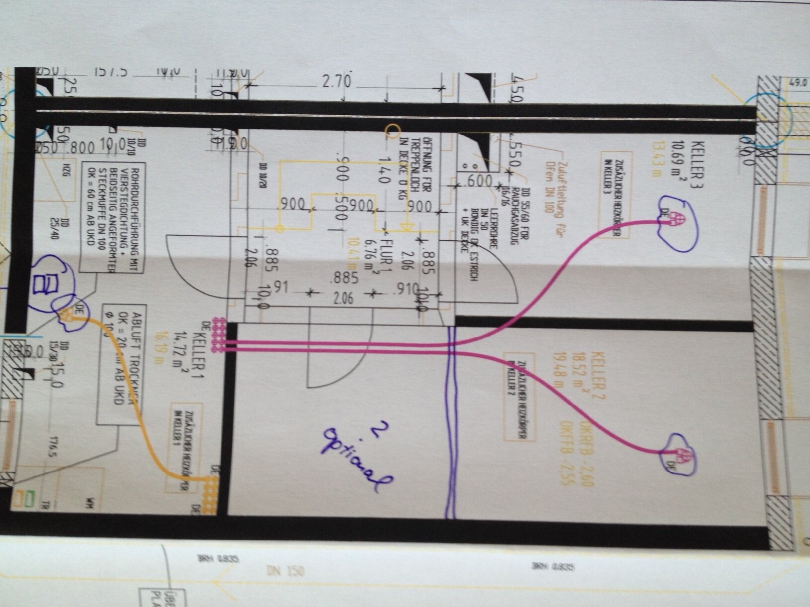
I have now received the finalized design for the central mechanical ventilation system with heat recovery from the specialist planner. It would be great if you could take a look and share your feedback. My main concern is the placement of the supply and exhaust air points. Unfortunately, we need to move quickly as the builder is applying pressure... 🙁
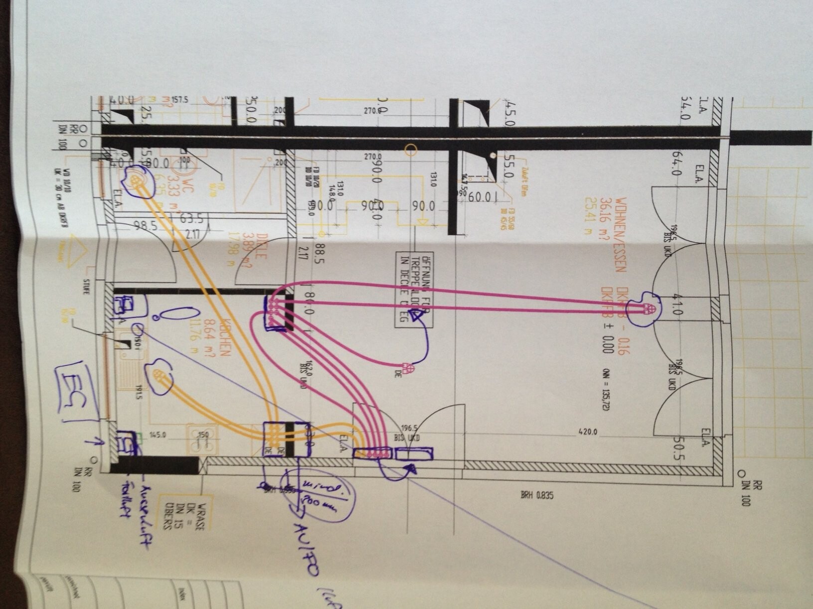
Magenta indicates supply air, and "orange/yellow" indicates exhaust air. Many thanks.
Best regards,
Robert
Here are the images:

I have now received the finalized design for the central mechanical ventilation system with heat recovery from the specialist planner. It would be great if you could take a look and share your feedback. My main concern is the placement of the supply and exhaust air points. Unfortunately, we need to move quickly as the builder is applying pressure... 🙁
Magenta indicates supply air, and "orange/yellow" indicates exhaust air. Many thanks.
Best regards,
Robert
Here are the images:
On the ground floor, I would recommend installing two outlets in parallel in the living room. Otherwise, the air volume required for the floor plan area for a single outlet becomes quite large.
On the first floor, I would place the valves not near the doors, but in the outer corners of the rooms (not exactly in the corner, but about 1 meter (3 feet) away from the wall). Otherwise, the air will blow in and flow directly towards the door, and in the bathroom, it will enter right near the door again. This means that no air exchange occurs in the other areas, or only limited exchange takes place.
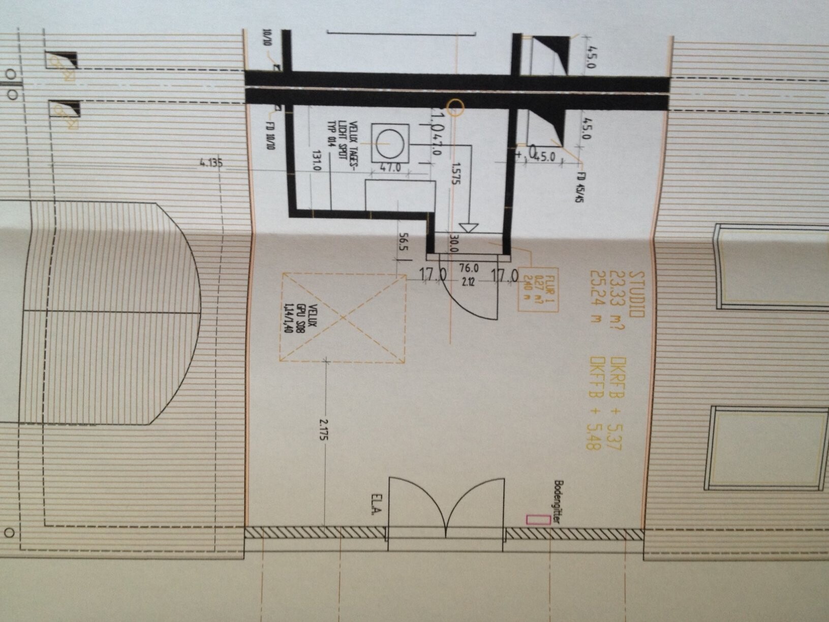
Have you planned anything for the attic? Our ventilation shaft vibrates and is noisy. I would never run it through bedrooms again. Why don’t you route it from the ground floor through the bathroom and upwards? That would make more sense – then the noise level is contained in the bathroom.
I’m surprised that the planning is not being done by the person who created and determined the ventilation concept?!
I have no idea if one outlet on the ground floor is really enough – something like this must be calculated.
On the first floor, I would place the valves not near the doors, but in the outer corners of the rooms (not exactly in the corner, but about 1 meter (3 feet) away from the wall). Otherwise, the air will blow in and flow directly towards the door, and in the bathroom, it will enter right near the door again. This means that no air exchange occurs in the other areas, or only limited exchange takes place.
Have you planned anything for the attic? Our ventilation shaft vibrates and is noisy. I would never run it through bedrooms again. Why don’t you route it from the ground floor through the bathroom and upwards? That would make more sense – then the noise level is contained in the bathroom.
I’m surprised that the planning is not being done by the person who created and determined the ventilation concept?!
I have no idea if one outlet on the ground floor is really enough – something like this must be calculated.
Hello and thank you for your feedback,
the design was created by a planner. He just wanted my approval.
In the attic, next to the floor-to-ceiling window, there is a floor grille for fresh air supply. I have already contacted the planner – he is now looking for a way to place the ducts into the bathroom and WC. Thank you very much for the tip!
I didn’t quite understand the part about the first floor...
Best regards,
Robert
Hampek schrieb:
I didn’t quite understand the part about the first floor...The air circulates: with three points, you have an inlet and an exhaust in the bathroom. If these points are located further outward, I would assume that the air exchange covers more of the stale air from the rooms.The green lines are supposed to represent the airflows.
Wastl schrieb:
If the locations are further outward, I would assume that the air exchange covers more of the stale air in the rooms... Correct, the ideal case is a room diagonal. Ultimately, it’s about effective air exchange. Negative example:
v.g.
W
wadenkneifer12 Jun 2014 17:24@€uro: Please tell me that your negative example is fabricated and that no one has actually planned or even built like that? :O
This is basically first-grade physics plus a few moments of logical thinking, right?
Best regards
Michael
This is basically first-grade physics plus a few moments of logical thinking, right?
Best regards
Michael
Similar topics