ᐅ Making Sensible Improvements to Existing Satellite/Cable Installations
Created on: 12 Jan 2021 23:47
R
RAL5018
This is the situation I found:
The old cable connection is no longer in use. The wiring ran from the main distribution point (MDP) up to the attic and from there, through a splitter, down to several rooms. The cables and outlets still mostly exist but are no longer connected.
Then a satellite system (quad LNB) was installed, and new cables were run. These cables are embedded in the walls without outlets in the rooms; they just protrude from the walls.
I am currently renovating and want to optimize this setup. I want to keep the satellite connection for now but also keep the option open to switch to cable TV later. Since it’s not easy to lead the satellite cables up to the attic and redistribute them from there (which would probably have been the best solution from the start, I guess), and the new satellite cables are already partially installed at low cost, I would simply install drop outlets (?) there. So far, so good. Or are there good reasons not to install any outlets at all?
If I have 1-2 free connections on the LNB and the cable runs close to the old distribution, I could connect a device to one of the old cable outlets by running a cable via some kind of outlet up to the attic, right? Would I need to modify the outlets in any way, or would that just work?
Can I also route the satellite cable in a room (where it’s not really needed) via a pass-through outlet (?) up to the attic and then star-connect 1-2 more outlets so that only one of them is used at a time? So only one device would ever be plugged in? Or is the mere presence of splitters/pass-through outlets without devices an issue?
Can I even use the same type of distribution for satellite and cable TV? (I understand that cable TV allows multiple devices to operate on a star splitter, while a star wiring with a quad LNB only allows one device to be used at a time.)
I hope it’s clear what I want? I’ll try to describe it differently. I imagine connecting a cable from the LNB to an outlet (pass-through?), and from there another cable running up to the attic (where the cable signal originally came from). The cable upstairs is currently not connected. I would like to connect this to another former cable outlet to be able to use either one or the other outlet.
Also, I still have the option to unplug the LNB and switch back to cable from the other side. Then the cable would probably have to be disconnected directly at the outlet or a terminating resistor would need to be added at the LNB? That’s okay… At this stage, I mainly want to arrange the outlets and cables so that I can easily feed one of the old outlets with one of the remaining LNB channels. Switching upstairs in the attic is not a problem, but of course, it would be nicer if it could work without that.
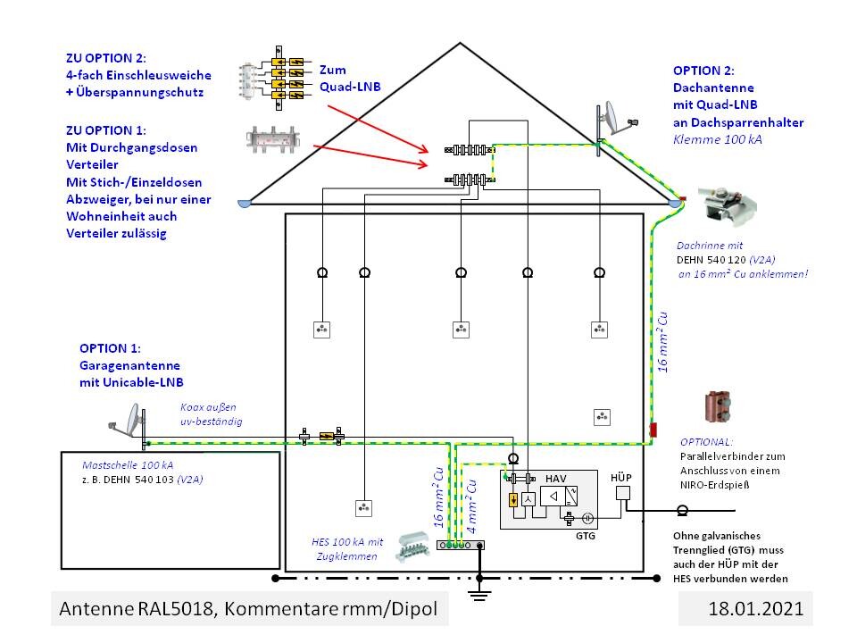
The sketch clears up the confusion.
Routing cables through the lightning protection zone LPZ 0A and even on the outside of the facade within the grounding-required 2 m (6.5 feet) zone shows a lack of lightning protection awareness by the installer and could only be topped by routing cables alongside a metal gutter (please provide a photo of that).
Even if this antenna location, which is unfavorable for high-frequency and lightning protection reasons, was specified by the client for aesthetic reasons, a standards-aware antenna installer should have raised concerns about performing the installation without a lightning-current-capable grounding and equipotential bonding and should have refused to proceed. Direct lightning strikes are fortunately rare, but if the patron saint of firefighters fails, no eye would remain dry here. Moreover, there is no basic protection against electric shock.
To propose a code-compliant solution in detail, information is still required on whether the mandatory equipotential bonding, enforced since the end of the transition period in 1990, has been implemented, and please also mark the position of the main earthing terminal (MET) (with grounding system?) on the sketch. Photos of the decommissioned cable TV system and the "bare" main earthing terminal without cover would help avoid further inquiries. The type and approximate length of the coaxial cables are also relevant.
- According to IEC 60728-11, the satellite antenna in this position must be grounded, and
- the cable routing upward along the facade also crosses the 2 m (6.5 feet) zone beneath the eaves, which is defined by standards as not lightning strike safe.
- A cable TV signal feed from the network interface device (NID) -> distribution point (HAV) -> new directional coupler pass-through socket -> one of the existing satellite cables -> cable TV four-way splitter in the attic -> new pass-through sockets + termination resistors is technically feasible.
- Subject to approval by the cable network operator, except for the satellite cable repurposed for the cable TV feed, satellite signals can also be injected into the other cables as long as the cable TV range does not exceed 1006 MHz.
Routing cables through the lightning protection zone LPZ 0A and even on the outside of the facade within the grounding-required 2 m (6.5 feet) zone shows a lack of lightning protection awareness by the installer and could only be topped by routing cables alongside a metal gutter (please provide a photo of that).
Even if this antenna location, which is unfavorable for high-frequency and lightning protection reasons, was specified by the client for aesthetic reasons, a standards-aware antenna installer should have raised concerns about performing the installation without a lightning-current-capable grounding and equipotential bonding and should have refused to proceed. Direct lightning strikes are fortunately rare, but if the patron saint of firefighters fails, no eye would remain dry here. Moreover, there is no basic protection against electric shock.
To propose a code-compliant solution in detail, information is still required on whether the mandatory equipotential bonding, enforced since the end of the transition period in 1990, has been implemented, and please also mark the position of the main earthing terminal (MET) (with grounding system?) on the sketch. Photos of the decommissioned cable TV system and the "bare" main earthing terminal without cover would help avoid further inquiries. The type and approximate length of the coaxial cables are also relevant.
Even though interest in standards-based advice seems to have faded, I am submitting a prepared renovation proposal for BK and BK with satellite feed into four participant outlets including
for consideration.
I find consultations difficult when you have to extract the necessary information from users seeking advice.
A waste of time.
- the existing garage antenna and a new unicable LNB, as well as
- antenna relocation to the roof using the existing quad LNB
for consideration.
I find consultations difficult when you have to extract the necessary information from users seeking advice.
A waste of time.

*Dipol* schrieb:
Consultations where you have to coax the necessary information out of users seeking advice are difficult for me. Same here. That makes me even more glad that you’ve managed to push through, because I always find these topics really interesting. I shake my head every time I see the nonsense the average electrician produces, who of course also has satellite and antenna systems installed on their van. By the way, for me this topic will be settled once the upcoming move is done. So I’m genuinely and honestly only interested due to the technical aspects, and because I always enjoy listening to or reading people who clearly know what they’re talking about. Keep it up!
Thank you very much for the detailed suggestions! I am still here and appreciate the advice.
Honestly, I am a bit overwhelmed by all this.
One reason I haven’t replied sooner is because I am not even able to provide all the requested information—let alone fully understand the diagram or draw the right conclusions from it.
At the moment, I don’t have the capacity to dive so deeply into this subject—I thought the question about wiring would be easy to answer. Only slowly am I beginning to understand that it’s not that simple, and why that is.
Therefore, please understand that I could not foresee which information would be needed, and I can’t supply some of the details at all.
For completeness, I will try to answer everything as much as I can:
The new coax cables are type “110 HD PVC - 17dB/100N@800MHz EN 50117-2-4, Class A - 100723” and are between 15 and 30 meters (approximately 50 and 100 feet) long, depending on the room.
The old coax cables are probably from the building year (~1982), and I wasn’t able to determine exactly what type these are. I estimate their length to be about 10–15 meters (approximately 33–50 feet), depending on the room.
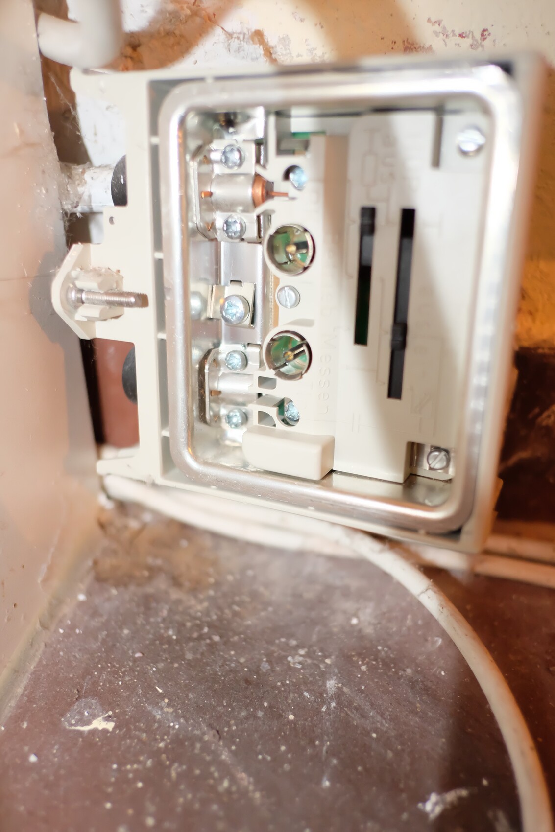
The main grounding bar is neither near the cable connection nor the satellite system. To my knowledge, there is no connection there either—but I can’t say for sure, as an electrician would have to inspect the box first... I won’t touch that.
I took a photo of the BK-HÜP. As mentioned, nothing is connected there. The cables around it are unrelated—the connected cable is probably the house connection, but the further routing is inaccessible.
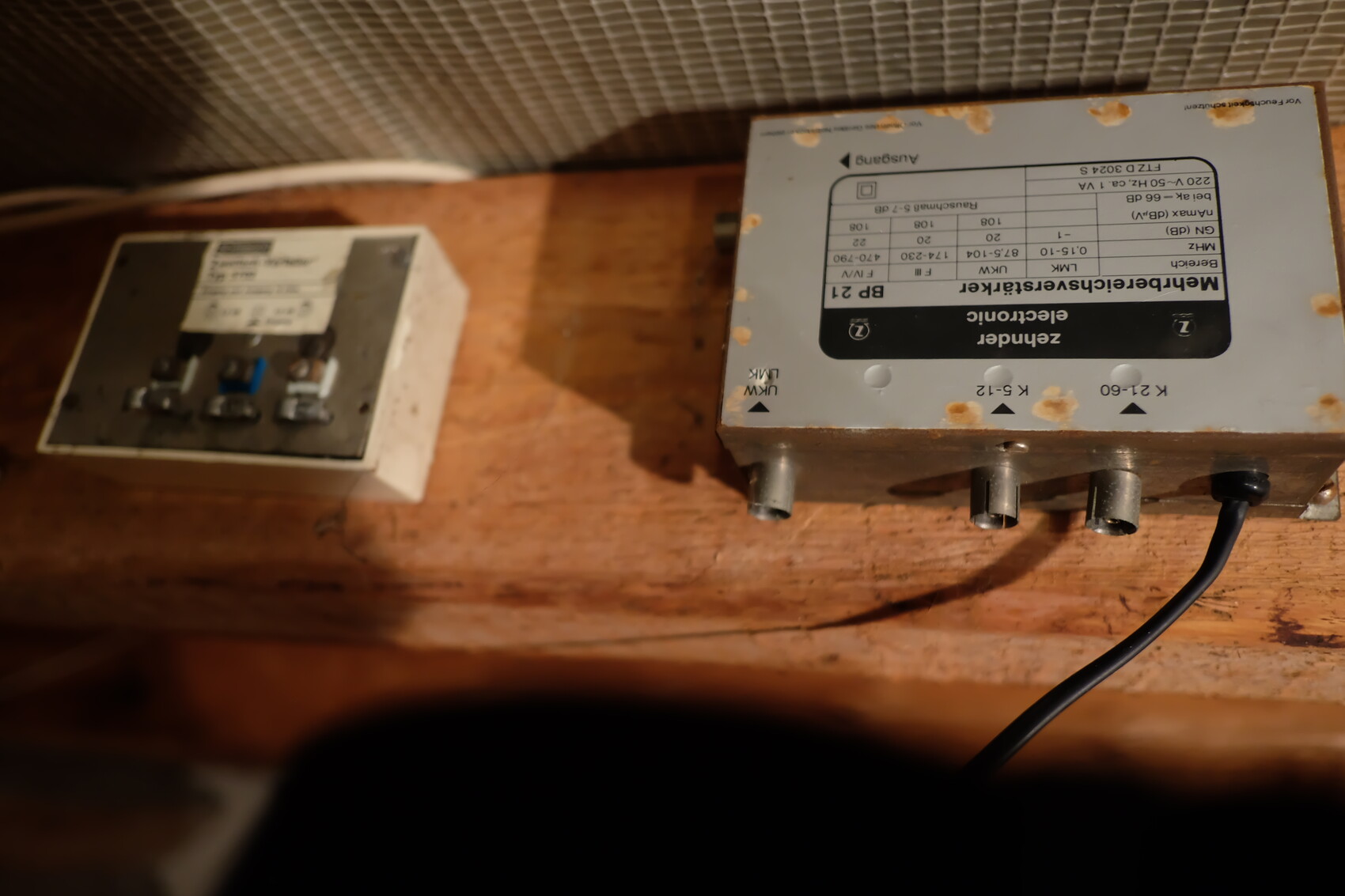
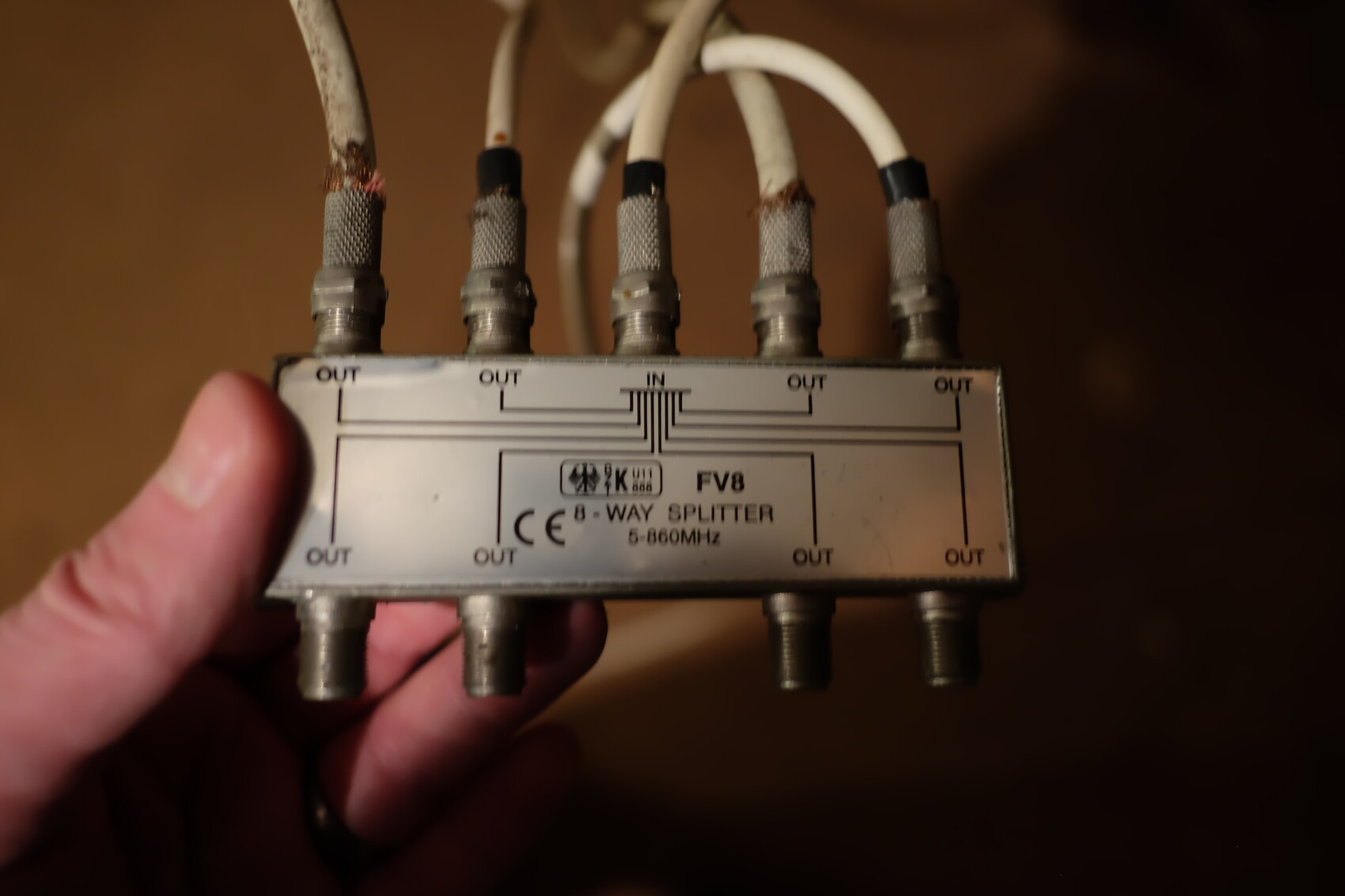
In the other pictures, you can see old splitters/amplifiers that are no longer in use.
Honestly, I am a bit overwhelmed by all this.
One reason I haven’t replied sooner is because I am not even able to provide all the requested information—let alone fully understand the diagram or draw the right conclusions from it.
At the moment, I don’t have the capacity to dive so deeply into this subject—I thought the question about wiring would be easy to answer. Only slowly am I beginning to understand that it’s not that simple, and why that is.
Therefore, please understand that I could not foresee which information would be needed, and I can’t supply some of the details at all.
For completeness, I will try to answer everything as much as I can:
The new coax cables are type “110 HD PVC - 17dB/100N@800MHz EN 50117-2-4, Class A - 100723” and are between 15 and 30 meters (approximately 50 and 100 feet) long, depending on the room.
The old coax cables are probably from the building year (~1982), and I wasn’t able to determine exactly what type these are. I estimate their length to be about 10–15 meters (approximately 33–50 feet), depending on the room.
The main grounding bar is neither near the cable connection nor the satellite system. To my knowledge, there is no connection there either—but I can’t say for sure, as an electrician would have to inspect the box first... I won’t touch that.
I took a photo of the BK-HÜP. As mentioned, nothing is connected there. The cables around it are unrelated—the connected cable is probably the house connection, but the further routing is inaccessible.
In the other pictures, you can see old splitters/amplifiers that are no longer in use.
RAL5018 schrieb:
For completeness, I will try to answer everything as best as I can: The new coax cables are of the type "110 HD PVC - 17dB/100m @ 800MHz EN 50117-2-4, Class A - 100723" and are between 15 and 30 meters (50 and 100 feet) long, depending on the room. The old coax cables are probably from the original construction year (~1982), and I couldn’t identify the exact type. I estimate their length to be about 10 to 15 meters (33 to 50 feet), depending on the room. - The 8-way splitter is designed for satellite intermediate frequency (IF) and
- the multiband amplifier is unsuitable for cable TV (CATV).
- Technically outdated F-type screw-on connectors, which only fit the cable diameter with the rough fix of insulation tape, are poor practice.
- I could not find the new cable type online,
- but 17 dB/100 m attenuation at 800 MHz indicates a low-loss foam dielectric.
- The number of shields,
- whether the inner conductor is made of low-quality copper-clad steel or copper,
- and whether the braid is aluminum prone to breakage and intermodulation or tinned copper,
can only be determined on-site by inspection.
Simply shielded old 60-ohm coax cables cause strong electromagnetic interference (EMI) and should be replaced even if they are short and show low signal attenuation. The EMI limits set by national standards and electromagnetic compatibility (EMC) regulations must be met even without disruptions to your own reception.
RAL5018 schrieb:
The main grounding bar is neither near the cable connection nor the satellite system. To my knowledge, there is no connection there – but I cannot say for sure; an electrician would first need to inspect the panel... I won’t attempt that. Better to retrofit a protective conductor system decades late than never, and this should include a grounding system for the antenna that complies with current standards.

@*Dipol*
Hello,
I live, like you, in the Stuttgart metropolitan area and operate a fairly extensive satellite system in my single-family home with an injected Vodafone (formerly Unitymedia) cable. I have a quick question regarding your explanation that the cable networks are expected to be extended up to 1006 MHz.
Would it be possible to install an Axing TZU 198-62 low-pass filter or a similar/better equivalent in the cable feed? This would block cable frequencies above 950 MHz and prevent interference in the satellite feed.
It’s clear that some cable channels would be lost, but I currently only use the cable connection for a few FM tuners.
Similar topics